Scanning Multimeter Instrument
The Scanning Multimeter instrument consists of an Agilent E1326B Multimeter and one or more multiplexer
modules. In this configuration, the multiplexer modules scan measurement channels and feed the signal
through the analog bus to the multimeter where the measurements take place. Programming is simplified
because one command controls both the measurement type and the channels to be scanned. The Scanning
Multimeter configuration is recommended when:
• Using the multimeter to make measurements on a series of channels (scanned channels).
• The fastest execution speed for scanned measurements is needed.
• Only one channel closure at a time is needed.
• Making thermocouple or strain measurements.
To create a Scanning Multimeter instrument, you set the multimeter module’s logical address to a multiple
of eight and assign the multiplexer modules successive logical addresses. You then connect the Analog Bus
cables between all modules (this is shown in detail later in Step 7).
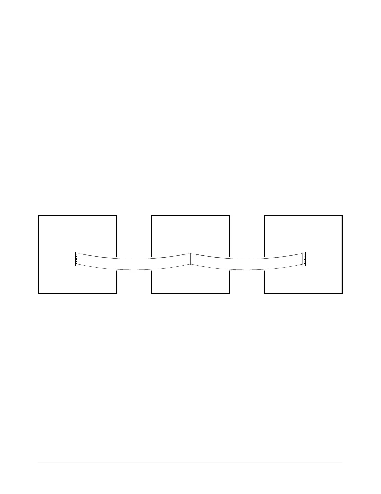
For example, as shown in Figure 1-2, if the multimeter’s logical address is 24, the multiplexers would be
25, 26, and so on. In this example, the Scanning Multimeter will be programmed at GPIB secondary
address 03. This address is derived by dividing the multimeter’s logical address by eight (24/8 = 03).
These multiplexer modules can be part of a Scanning Multimeter:
E1343A 16-Channel High Voltage Multiplexer
E1345A 16-Channel Relay Multiplexer
E1346A 48-Channel Single Ended Relay Multiplexer
E1347A 16-Channel Thermocouple Relay Multiplexer
E1351A 16-Channel FET Multiplexer
E1352A 32-Channel Single-Ended FET Multiplexer
E1353A 16-Channel Thermocouple FET Multiplexer
E1355A 8-Channel 120Ω Strain Relay Multiplexer
E1356A 8-Channel 350Ω Strain Relay Multiplexer
E1357A 8-Channel 120Ω Strain FET Multiplexer
E1358A 8-Channel 350Ω Strain FET Multiplexer
Agilent E1345A
16-Channel
Relay Multiplexer
Agilent E1345A
16-Channel
Relay Multiplexer
Logical Address = 25
Logical Address = 26
Agilent E1326B
5 1/2 Digit Multimeter
Logical Address = 24
Secondary Address = 03
Analog Bus Cable Analog Bus Cable
Figure 1-2. Scanning Multimeter Instrument Block Diagram
Installing the System 1-7

 Loading...