Step 5: Set Plug-In Module Logical Addresses
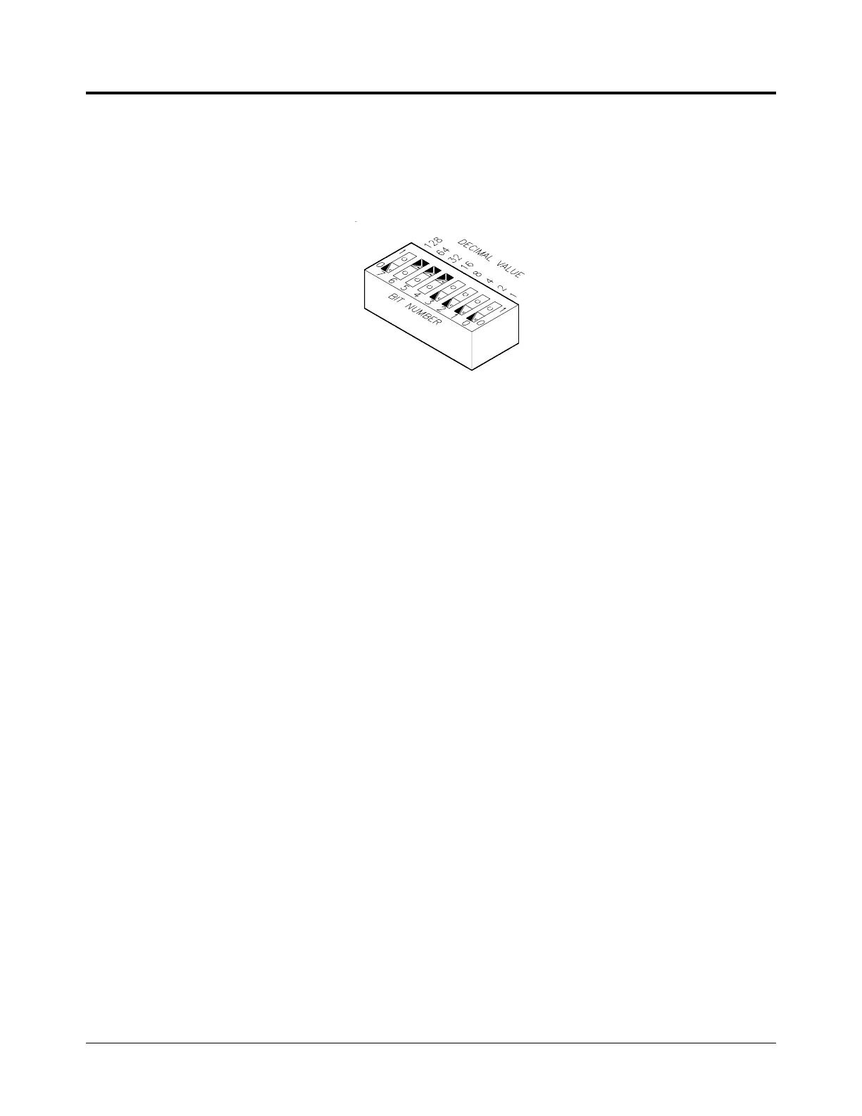
As shown in Figure 1-4, a logical address switch contains eight individual switches. To determine the
logical address, add together the decimal values of the switches that are set (position 1 = set, 0 = not set).
For example, in Figure 1-4, switches 4, 5, and 6 are set, the other switches are not set. The logical address
is the sum of the decimal values of the set switches: 16 + 32 + 64 = 112.
Guidelines for Setting Logical Addresses
• Each plug-in module must have a unique logical address. If you have modules with the same
factory-set logical address, you must change some logical addresses so that each module has a
different address.
• Each instrument, whether single or multiple module, must have one module assigned as an
instrument identifier. The instrument identifier is the module with its logical address set to a multiple
of 8, such as 8, 16, or 24. An instrument’s secondary address (used to program the module from
GPIB) is derived by dividing the instrument identifier by 8. For example, a logical address of 24 is a
secondary address of 03.
• Examples showing the settings for a single module instrument, a multiple module Switchbox
instrument, and a Scanning Multimeter instrument are shown on the following pages.
• A plug-in module with a logical address that is not a multiple of 8, or that is not part of a Scanning
Multimeter or Switchbox instrument, is an unassigned module. Such modules must be programmed at
the register level, rather than with SCPI commands.
Figure 1-4. Logical Address Switch
Installing the System 1-9

 Loading...