Switchbox Instrument
The Switchbox instrument is composed of one or more switch modules. The single module Switchbox
behaves as an independent instrument as described earlier. When using the multiple module Switchbox, all
switch modules are programmed together and behave as if they are one instrument. The multiple module
Switchbox configuration is recommended when you need to:
• Simplify the programming of multiple switch modules.
• Group multiplexers together to create a larger multiplexer.
• Make scanned measurements but are not using the Agilent E1326B Multimeter (if you are using the
Agilent E1326B, use the Scanning Multimeter configuration).
• Close channels on more than one module simultaneously.
To create a multiple module Switchbox, set one switch module’s logical address to a multiple of eight and
assign the other switch modules successive logical addresses. If applicable, you then connect the Analog Bus
cables between all modules (this is shown in detail later in Step 7).
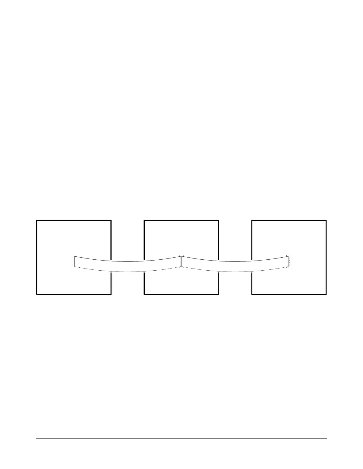
Figure 1-3 is a block diagram example of a Switchbox instrument containing three multiplexers. In this
example, one multiplexer has a logical address of 112, the other multiplexers have successive logical
addresses of 113 and 114. The multiplexers are linked together using the Analog Bus to form a larger
(48-channel) multiplexer. In this example, the Switchbox will be programmed at GPIB secondary address
14. This address is derived by dividing the first multiplexer’s logical address by eight (112/8 = 14).
These modules can be used to form a Switchbox:
Analog Bus CableAnalog Bus Cable
Agilent E1345A
16-Channel
Relay Multiplexer
Agilent E1345A
16-Channel
Relay Multiplexer
Agilent E1345A
16-Channel
Relay Multiplexer
Logical Address = 112
Secondary Address = 14
Logical Address = 113
Logical Address = 114
Figure 1-3. Switchbox Instrument Block Diagram
E1343A 16-Ch. High Voltage Multiplexer
E1344A 16-Ch. Thermocouple High Volt Multiplexer
E1345A 16-Ch. Relay Multiplexer
E1346A 48-Ch. Single Ended Relay Multiplexer
E1347A 16-Ch. Thermocouple Relay Multiplexer
E1351A 16-Ch. FET Multiplexer
E1352A 32-Ch. Single-Ended FET Multiplexer
E1353A 16-Ch. Thermocouple FET Multiplexer
E1355A 8-Ch. 120
Ω Strain Relay Multiplexer
E1356A 8-Ch. 350
Ω Strain Relay Multiplexer
E1357A 8-Ch. 120
Ω Strain FET Multiplexer
E1358A 8-Ch. 350
Ω Strain FET Multiplexer
E1361A 4 x 4 Relay Matrix
E1364A 16-Ch. Form C Switch
E1366A 50
Ω RF Multiplexer (2 x 4:1)
E1367A 75
Ω RF Multiplexer (2 x 4:1)
E1368A 18 GHz Microwave Switch
E1369A Microwave Switch Driver
E1370A Switch Microwave/Attenuator Driver
1-8 Installing the System

 Loading...