Measurement Techniques
46
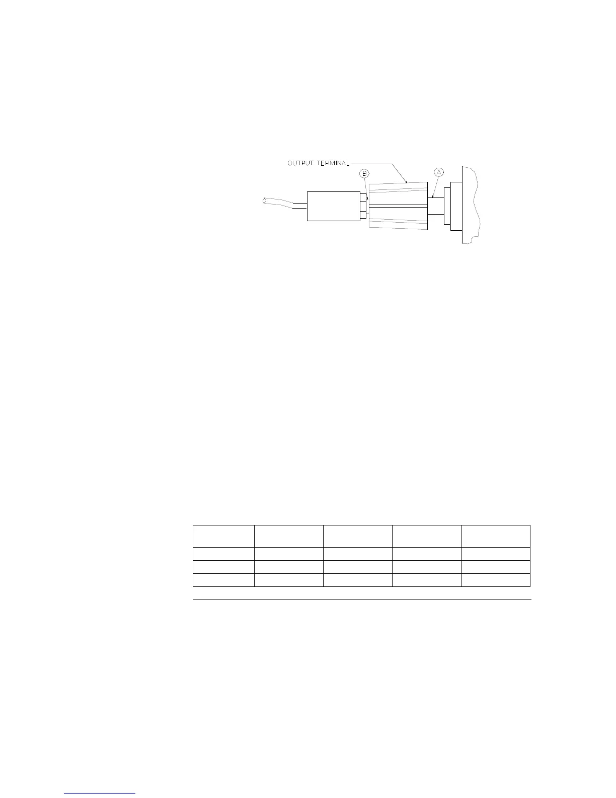
load resistor is plugged into the front of the output terminals at (B). A
measurement made across the load includes the impedance of the leads to the
load. The impedance of the load leads can easily be several orders of the
magnitude greater than the power supply impedance and thus invalidate the
measurement. To avoid mutual coupling effects, each measuring device must
be connected directly to the output terminals by separate pairs of leads.
Front Panel Terminal Connections (Side View)
Current-Monitoring Resistor
To eliminate output current measurement error caused by the voltage drops
in the leads and connections, connect the current monitoring resistor between
the (-) output terminal and the load as a four-terminal device. Connect the
current-monitoring leads inside the load-lead connections directly at the
monitoring points on the resistor element (see R
M
in Figure 3-1).
Programming
Most performance tests can be performed only from the front panel. However,
a GPIB or RS-232 controller is required to perform the voltage and current
programming accuracy and readback accuracy tests.
The test procedures are written assuming that you know how to program the
power supply either from the front panel or from an GPIB or RS-232 controller.
Complete instructions on front panel and remote programming are given in the
Agilent E3631A User's Guide.
Voltage and Current Values
The full-scale and maximum values of each supply are listed below. You can
use this table when you test CV and CC performance verification tests.
Table 3-2 Power Supply Voltage and Current Values
Output
Full-Scale
Voltage
Max. Prog.
Voltage
Full-Scale
Current
Max. Prog.
Current
+6V Output +6 V +6.18 V 5 A 5.15 A
+25V Output +25 V +25.75 1 A 1.03 A
-25V Output -25 V -25.75 1 A 1.03 A

 Loading...