14
www.agilent.com/find/esg
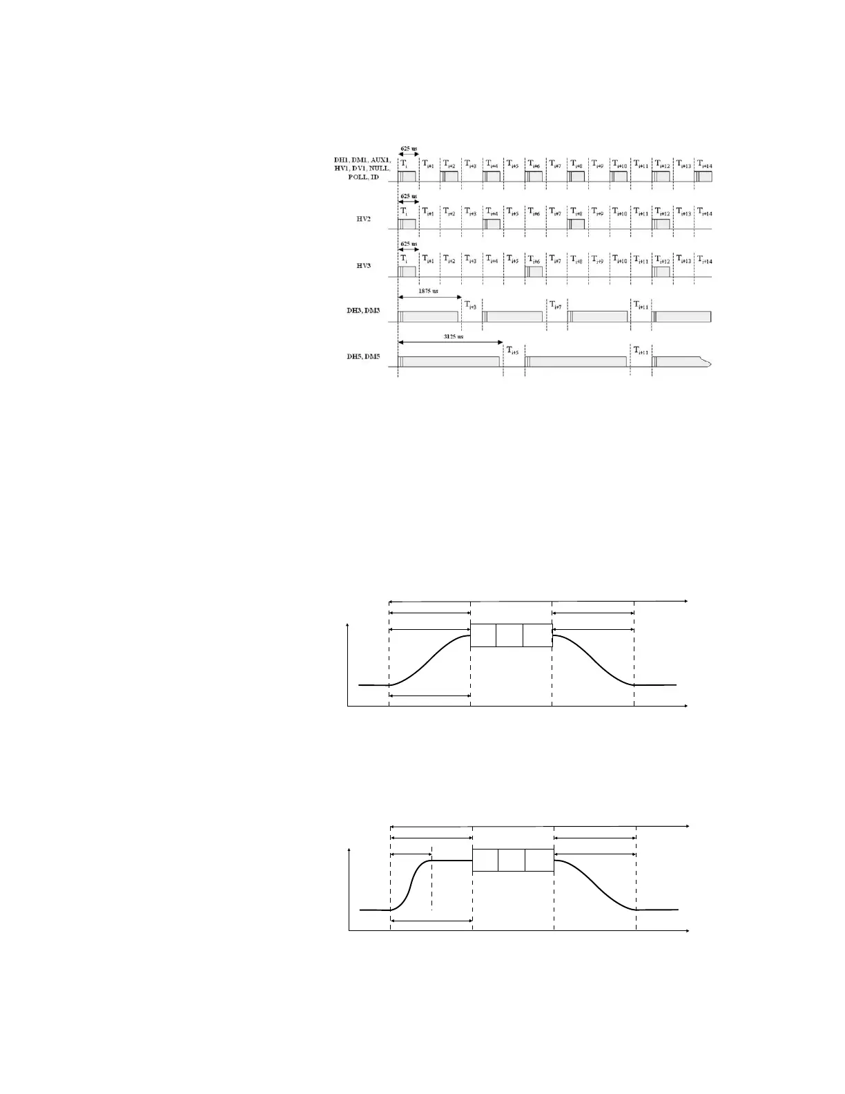
Figure 13. Bursted transmission timing relationships for different packet types.
At the beginning and end of a packet transmission, the ESG ramps power following a
user-defined burst profile. The burst profile is defined by setting the Power Ramp and
Ramp Settling fields with the desired time duration (in microseconds). See Figure 13.
The ramp profile is the duration of time prior to the first symbol transmission, over
which the carrier frequency is ramped from idle power to transmit power. The power
ramp is shaped with a cosine function, and length of the ramp can be adjusted. The
Ramp Settling field sets the length of time allowed for the power level to stabilize prior
to the first symbol transmission of the first bit of the preamble, t
po
. The settling time
includes the power ramp time as indicated in the Bluetooth specification, see section
6.2.2 of the SIG’s RF Test Specification under the “Reference Signal Definition” section.
The default settings of a 6 µs power ramp and ramp settling time produce the ramp
profile shown in Figure 14.
Figure 14. Burst profile of a single slot packet transmission with 6 µs power ramp and ramp settling.
A reference burst profile for signal generator test signals is indicated in the Bluetooth
RF test specification. This burst profile is recommended when performing the dirty
transmitter test. The reference burst power ramp is 2 µs and the ramp settling time
is 4 µs. This ramp profile is shown in Figure 15.
Figure 15. Burst profile of a single slot packet transmission with 2 µs power ramp and 4 µs ramp settling.
Creating Signals
Time
Power
Tx Timeslot period = 625 µs
Access
Code
Header
Payload
6 µs
power ramp
down
power settling
6 µs
6 µs
power ramp
up
t
po
Time
Power
Tx Timeslot period = 625 s
Access
Code
Header
Payload
power settling
4s
4 s
power ramp
up
2s
t
po
4s
power ramp
down

 Loading...


