36
www.agilent.com/find/esg
BER measurement setup
The ESG does not establish a link with a Bluetooth device; however, different BER
measurement setups can still be achieved on Bluetooth devices that internally implement
various test modes. These test modes do not require a link to be established. The most
common are the “continuous receive” test modes and a “loopback” test modes.
Measurement setups for both are discussed below.
“Continuous receive” operating mode
A Bluetooth device in “continuous receive” operating mode must provide access to the
demodulated Bluetooth signal in order to perform BER measurements. Access is typically
provided at the FM demodulator or baseband processor output. The ESG BER analyzer
data input impedance is TTL and CMOS compatible. The input thresholds to option UN7
are adjustable. The acceptable Hi/Lo thresholds are as follows:
0.7 V [TTL]
1.4 V [TTL]
1.65 V [CMOS 3.3]
2.5 V [CMOS 5.0]
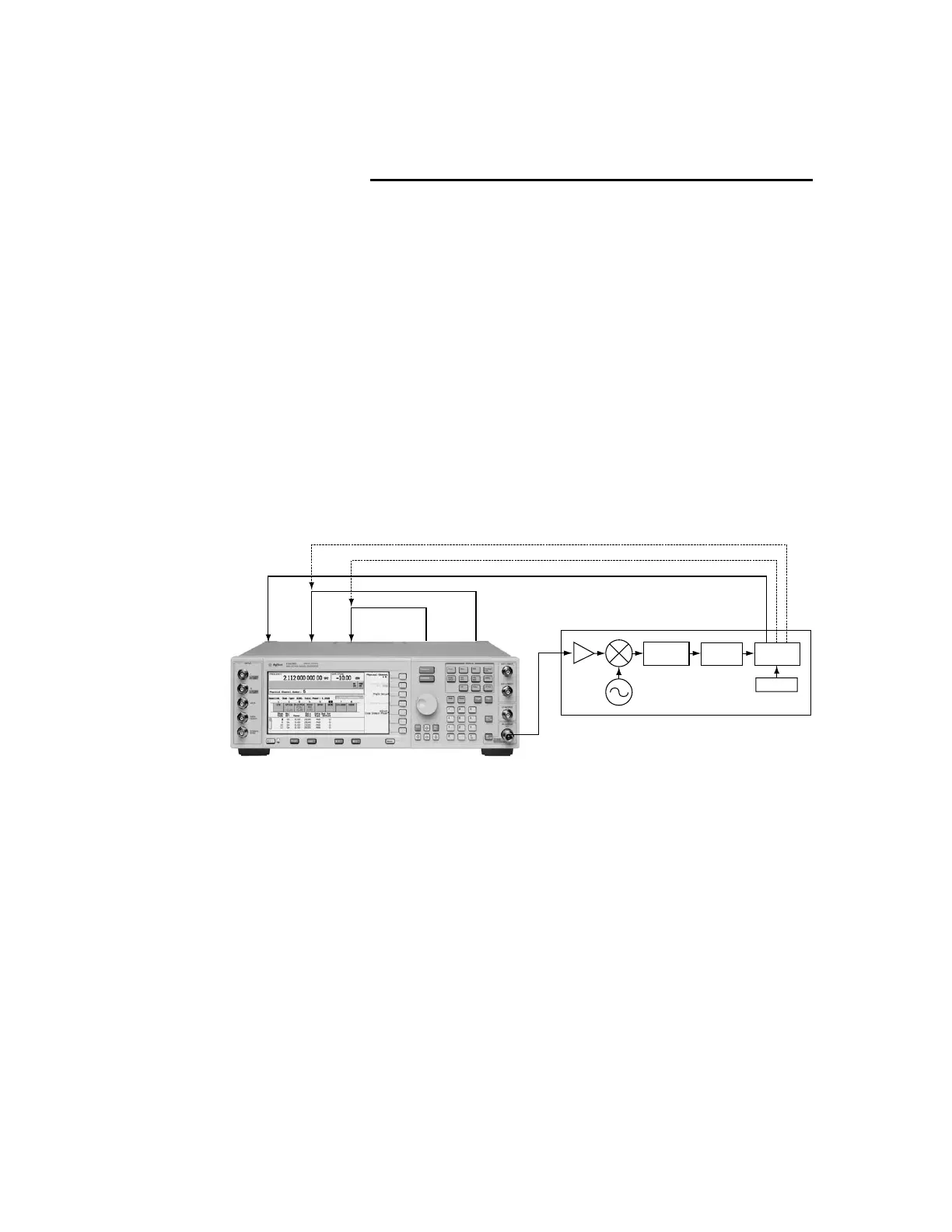
An example BER measurement setup is illustrated in Figure 40. In this setup, the ESG is
configured to provide a Bluetooth modulated RF signal using Signal Studio. The RF test
signal consists of a sequence of Bluetooth modulated DH1 packets with continuous PN9
payload data.
Figure 40. BER test setup for a Bluetooth device in “continuous receive” operating mode.
Note: Dashed lines indicate alternate configurations.
Basic Measurements
E4438C ESG vector signal generator
• Option 503 250 kHz to 3 GHz frequency range
• Option 602 Baseband generator with 64 MSa
• Option 406 Signal Studio for Bluetooth
• Option UN7 Internal BER analyzer
BER
gate in
Event 2BER
data in
BER
clock in
Event 1
RF out
Bluetooth radio
receiver section
Rear panel
FM
demodulator
Threshold
detector
Baseband
processor
Control
Clock
Gate
Data

 Loading...


