Chapter 5 287
Concepts
Tuned RF Level Measurement Concepts
constant during the calibration. Then the two levels (reference level and PSA
level) are compared to get a ratio (noted as CF1, Cal Factor for Range1). The ratio
of the two measurements is stored as a calibration factor.
First RF Input Ranging Calibration
When the power of the input signal is lowered to the 2nd range (which varies by
different frequency band in the PSA), the Measuring Receiver creates a second
calibration factor (as CF2, Cal Factor for Range2) by comparing the power level
measured before and after the range changes. (The input signal level must not
change during this recalibration.) This new calibration factor CF2 is multiplied by
the calibration factor CF1 made previously (with the reference) to be used in all
subsequent measurements in RF range2 at that frequency.
• When IFBW = 10Hz, once SNR < 10dB, IFBW will be set to 1 Hz
automatically in order to measure lower levels.
• If 110 option is detected, Preamp is always set to OFF in range 3 while center
frequency is from 100KHz to 10MHz.
• While N5532A/B is connected:
When the initial source power >+16dBm, Preamp is always set to OFF
in range 3;
When the initial source power < +16dBm, Preamp is always set to ON
in range 3.
• Range 3 attenuator is fixed at 4 dB.
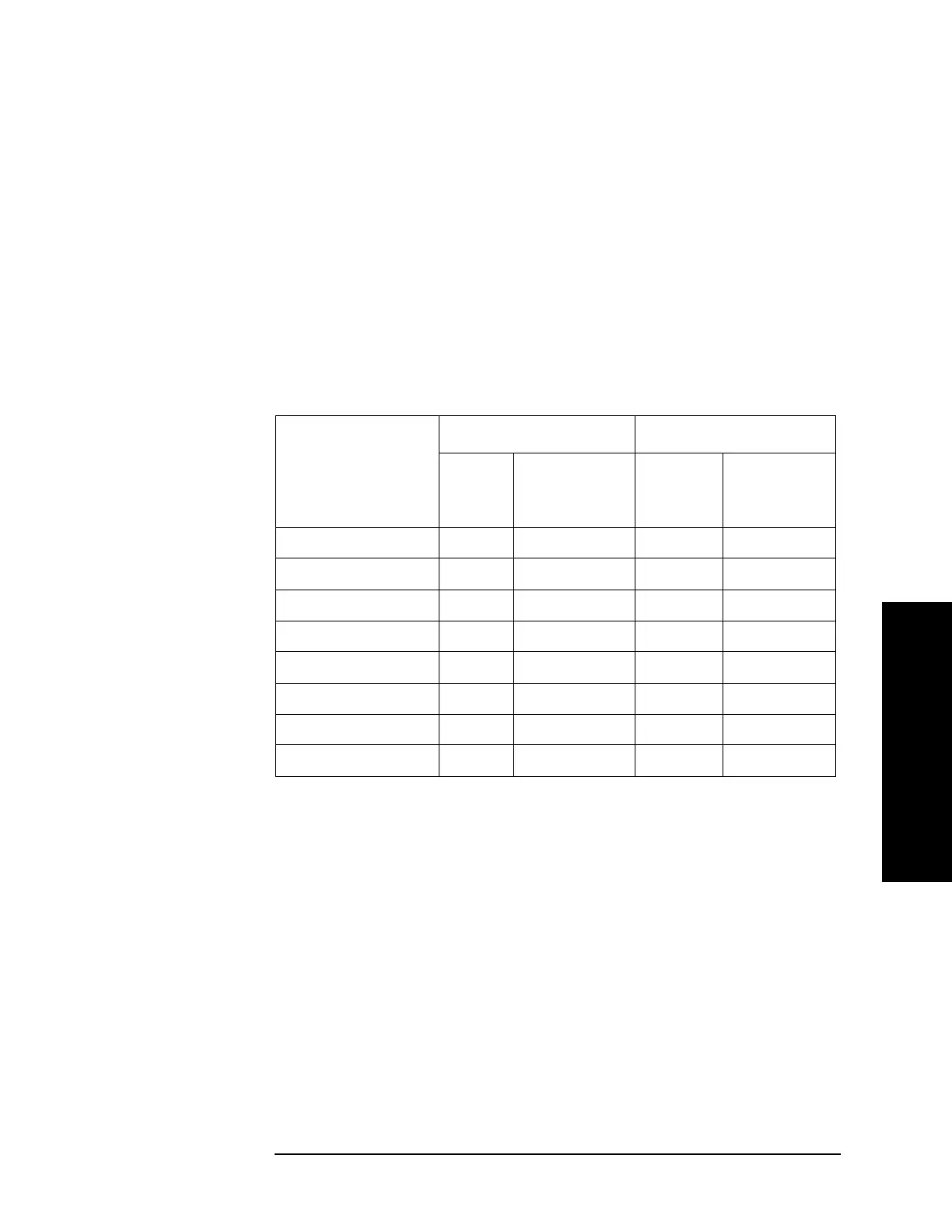
Table 5-1 SNR vs. PSA Ranging
Frequency Bands IF BW 75 Hz IF BW 10 Hz
SNR
(dB)
PSA
Attenuator
(dB)
SNR (dB) PSA
Attenuator
(dB)
100 kHz - 3.05 GHz 45 10 45 10
3.05 GHz - 6.6 GHz 45 10 45 10
6.6 GHz - 13.2 GHz 45 10 45 10
13.2 GHz -19.2 GHz 45 10 45 10
19.2 GHz -26.5 GHz 45 4 45 10
26.5 GHz - 31.1GHz 45 4 45 4
31.1 GHz - 41 GHz 40 4 45 4
41 GHz - 50.0 GHz 30 4 30 4

 Loading...


