Agilent N5161A/62A/81A/82A/83A MXG Signal Generators Service Guide
Troubleshooting
The RPG Knob is Not Functioning (N5181A/82A/83A)
1-61
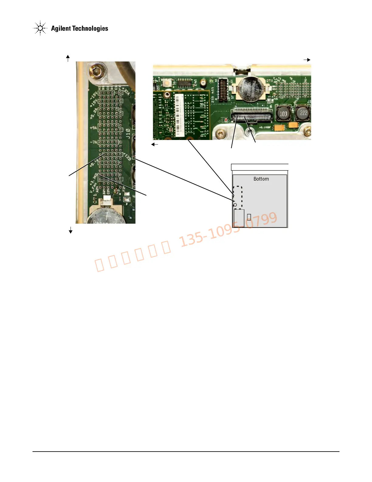
Figure 1-29 A3J6 and A3J10
If the RPG test fails, complete the following procedure to determine the faulty assembly/part:
1. Remove the front panel. Refer to Chapter 3, "Assembly Replacement".
2. Refer to Figure 1-28. Verify that A6J2-25 has a voltage of +3 Vdc:
• If A6J2-25 has a voltage of +3 Vdc, go to step 10.
• If A6J2-25 does not have a voltage of +3 Vdc, go to step 3.
3. Refer to Figure 1-28. Measure A6J1-11 and A6J1-12; they should have a voltage of +3 Vdc.
• If A6J1-11 and A6J1-12 have a voltage of +3 Vdc, replace the A6 DC-AC Inverter Interface Board.
• If A6J1-11 and A6J1-12 do not have a voltage of +3 Vdc, go to step 4.
4. Refer to Figure 1-29. Measure A3J6-11 and A3J6-12; they should have a voltage of +3 Vdc.
• If A3J6-11 and A3J6-12 have a voltage of +3 Vdc, replace the W1 ribbon cable.
• If A3J6-11 and A3J6-12 do not have a voltage of +3 Vdc, go to step 5.
5. Refer to Figure 1-29. Measure A3J10-A21 and A3J10-A22; they should have a voltage of +3 Vdc.
• If A3J10-A21 and A3J10-A22 have a voltage of +3 Vdc:
a. Replace the A3 RF assembly.
b. After replacing the A3 RF assembly in a model N5183A instrument, go to Chapter 4, "Post-Repair Procedures and Performance
Verification".
• If A3J10-A21 and A3J10-A22 do not have a voltage of +3 Vdc, go to “A1 Power Supply” on page 1-26 to troubleshoot the A1
Power Supply.
6. Refer to Figure 1-28. Measure A6J2-28; it should have a voltage of +5 Vdc.
• If A6J2-28 has a voltage of +5 Vdc, go to step 10.
• If A6J2-28 does not have a voltage of +5 Vdc, go to step 7.
A3J611 and A3J6-12
A3J10-A21 and A3J10-A22
Front Panel
Rear Panel
Rear Panel
Front Panel
A3J6-3 and A3J6-4
A3J10-B16
 Loading...


