Do you have a question about the Agilent Technologies N5700 Series and is the answer not in the manual?
Covers general safety rules, power-on checks, grounding, and specific warnings.
Explanation of graphical symbols used for safety warnings.
Summarizes the content and purpose of each chapter in the user's manual.
Provides a high-level overview of the Series N5700 DC Power Supplies.
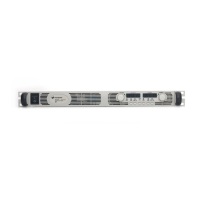
Details all components and controls on the front panel of the power supply.
Details all interfaces, connectors, and switches on the rear panel.
Covers models, items supplied, and available accessories for installation.
Details safety, environment, airflow, rack mounting, and cleaning for installation.
Instructions for connecting the AC power cord to the unit.
Guidance on connecting loads, including wire size selection.
Details on setting up local and remote voltage sensing connections.
Discusses multiple loads, noise, and inductive load considerations.
Instructions for connecting multiple units in parallel or series.
Provides pin assignments and functions for the J1 analog programming connector.
Step-by-step guide to verify the power supply operates correctly.
Describes constant voltage and constant current operating modes.
Details over-voltage, under-voltage, and over-temperature protection.
Explains how to control the output using front panel and remote methods.
Using analog signals for programming voltage, current, and monitoring.
Guides for connecting via GPIB, USB, and LAN interfaces.
Procedures for configuring IP addresses, hostnames, and network settings.
Basic concepts of the Standard Commands for Programmable Instruments (SCPI).
A summary of all subsystem and common SCPI commands.
Commands used to enable, disable, and perform calibration procedures.
Commands for measuring output voltage and current.
Commands related to output state, power-on, and protection functions.
Commands to set voltage, current, and protection levels.
Commands for programming and querying status registers.
Commands for controlling system functions like communication and errors.
Commands used to initiate and control triggering operations.
Example Visual Basic code for setting output voltage, current, and protection.
Example Visual Basic code for setting up and executing triggers.
Warranted technical specifications for the power supply models.
Descriptions of typical performance characteristics and parameters.
Provides dimensional drawings and physical layout of the unit.
Tests to verify the power supply is operating normally and within specs.
Step-by-step instructions for calibrating the power supply.
Details on service types, repackaging for shipment, and troubleshooting.
A list and explanation of instrument error codes and messages.
Compares N5700 compatibility command behavior with 603xA models.
Lists compatible commands and their SCPI equivalents.
| Number of Outputs | 1 |
|---|---|
| Operating Temperature | 0 to 50 °C |
| Storage Temperature | -40 to 70 °C |
| Cooling Method | Forced Air |
| Input Voltage | 100-240 VAC |
| Interface | GPIB, USB, LAN |
| Input Frequency | 47 to 63 Hz |