2 Installation
46 Model N6705 User’s Guide
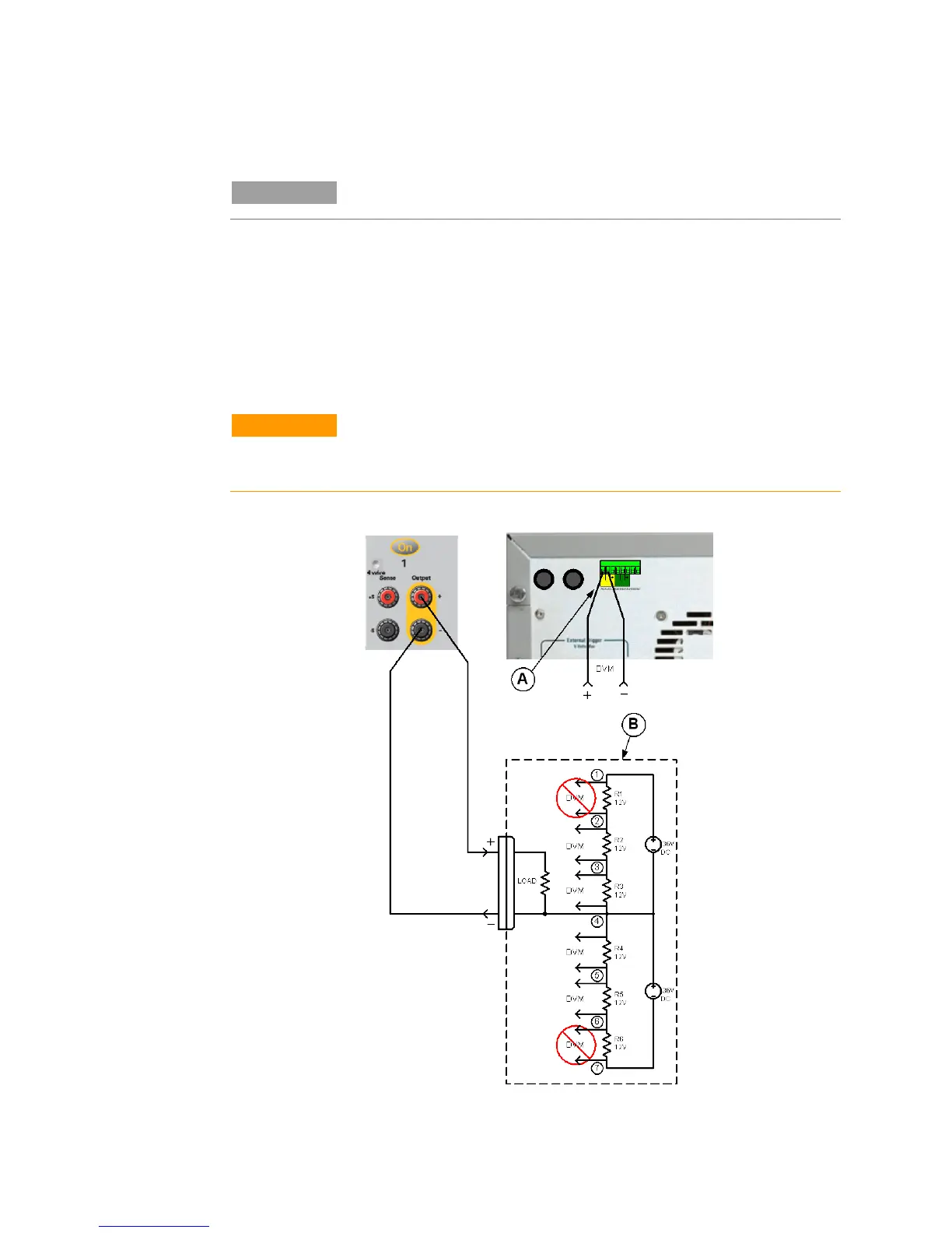
Connecting the Auxiliary Voltage Measurement Input
NOTE
This information applies to Agilent Model N6781A only.
The auxiliary voltage measurement input is located on the rear panel
of the Agilent N6705B. It is primarily used for battery voltage
rundown measurements, but it is also suitable for general purpose
DC measurements between ±25 VDC. As shown in the following
figure, auxiliary voltage measurements cannot be made on test points
that are at a greater potential than ±25 VDC from Common.
Refer to chapter 4 under “Agilent N6781A Auxiliary Voltage
Measurements” for more information.
CAUTION
When using the auxiliary voltage measurement input on Model N6781A, no
front panel output terminal or rear panel input terminal may be more than ± 60
VDC from any other terminal and chassis ground.
A. Aux Voltage
Measurement
input
B. Test Fixture
1. 36 V
2. 24 V
3. 12 V
4. Com.
5. –12 V
6. –24 V
7. –36 V