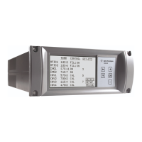
XGS-600 Gauge Controller
DRAFT 4/15/14
43
4. Lift the sensor board by the tab at the rear panel (Figure 4-2). Once the board is
disengaged from the board connector, pull the board out of the end guide.
Figure 4-2 Tab and Main Board Connector
WARNING To ensure safety and proper operation, no slot opening can be
left unfilled. Install a filler plate by installing the two hooks into
the case bottom and snapping in the foot.
Contact Agilent if additional fillers are needed.
5. Install the replacement board:
a. Place the end of the board into the end guide (Figure 4-3).
Figure 4-3 End Guide and HFIG Connector
b. Guide the board down as straight as possible onto the connector on the main
board. Figure 4-4 shows the connector on the base of all three board types.
Figure 4-4 Sensor Board Connector: Bottom View
End Guide
HFIG Plug
HFIG Power Cable

 Loading...