pg 14
Electrical Continued...
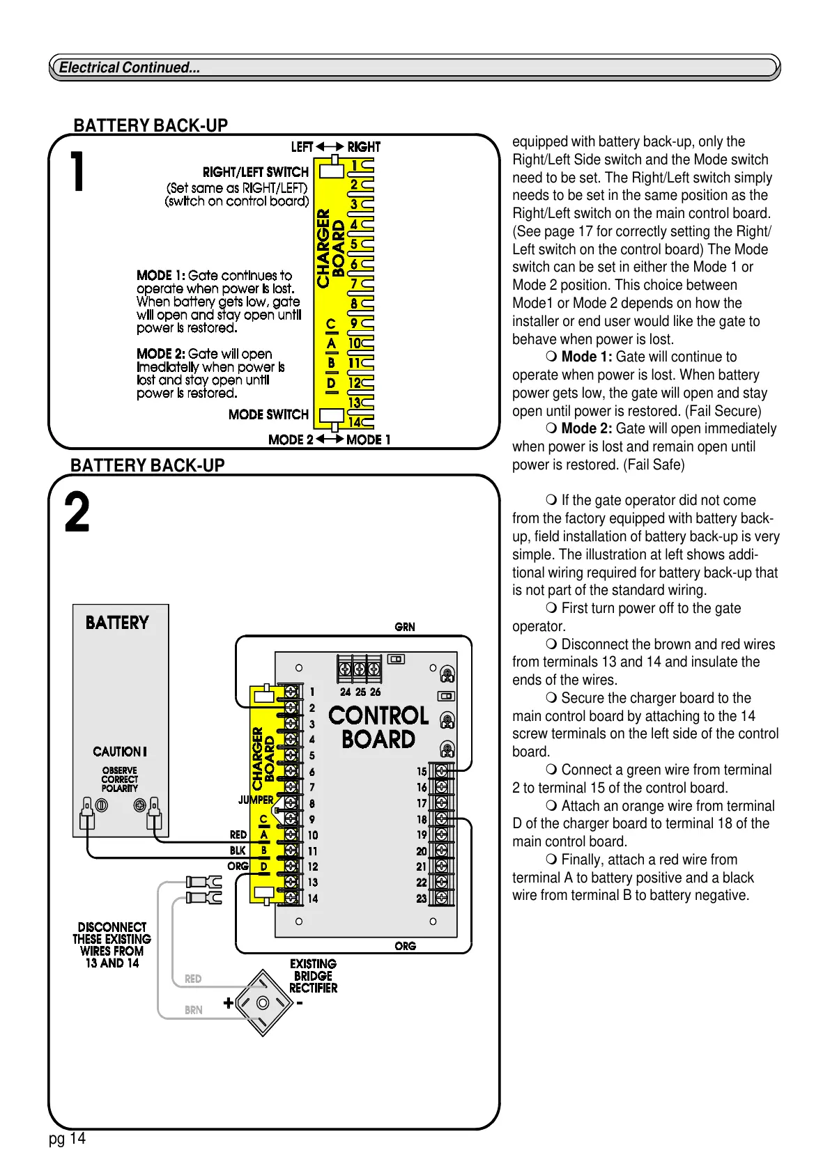
equipped with battery back-up, only the
Right/Left Side switch and the Mode switch
need to be set. The Right/Left switch simply
needs to be set in the same position as the
Right/Left switch on the main control board.
(See page 17 for correctly setting the Right/
Left switch on the control board) The Mode
switch can be set in either the Mode 1 or
Mode 2 position. This choice between
Mode1 or Mode 2 depends on how the
installer or end user would like the gate to
behave when power is lost.
m Mode 1: Gate will continue to
operate when power is lost. When battery
power gets low, the gate will open and stay
open until power is restored. (Fail Secure)
m Mode 2: Gate will open immediately
when power is lost and remain open until
power is restored. (Fail Safe)
m If the gate operator did not come
from the factory equipped with battery back-
up, field installation of battery back-up is very
simple. The illustration at left shows addi-
tional wiring required for battery back-up that
is not part of the standard wiring.
m First turn power off to the gate
operator.
m Disconnect the brown and red wires
from terminals 13 and 14 and insulate the
ends of the wires.
m Secure the charger board to the
main control board by attaching to the 14
screw terminals on the left side of the control
board.
m Connect a green wire from terminal
2 to terminal 15 of the control board.
m Attach an orange wire from terminal
D of the charger board to terminal 18 of the
main control board.
m Finally, attach a red wire from
terminal A to battery positive and a black
wire from terminal B to battery negative.
BATTERY BACK-UP
BATTERY BACK-UP