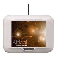
Use the 3 x pan head self-tapping Phillips screws supplied to fix the wall mounting bracket to the rear face
of the modem. Then use drywall screws to mount the Modem on the wall.
PSU CONNECTION
The modem is reverse polarity protected, but always refers to the drawing below to connect the power
adapter through the 2-way screw terminal correctly.
Connect the cable marked red to the V+ terminal and connect the yellow one to the V- terminal.
Plug the power adapter into the Mains supply.
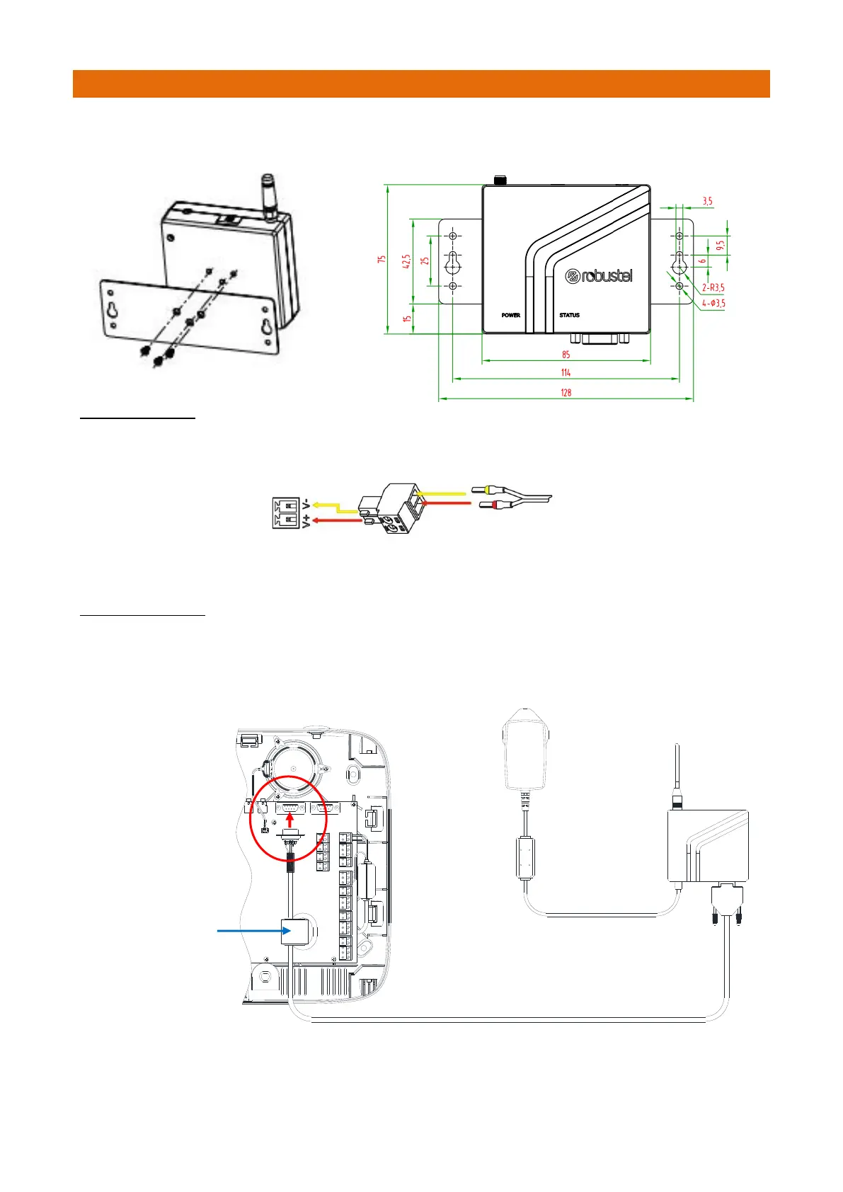
DATA CONNECTION
Plug shrouded 9 pin “D” plug end of the Data Cable into the Modem and finger-tighten the jack screws.
Route the Data Cable to the Touchsafe Pro Master Panel and plug the un-shrouded 9 pin “D” plug into
COM1 (as shown below). The 5m Data Cable can be cut-down in length but DO NOT extend any longer.