SDM4
SDM3
SDM2
SDM1
ABS zero
Zero point of work-piece (0.000)
X0
Y0
X
1 32
-
+
CLS Arc
sin
TOOL
0.000
SDM200
Press to input the number of machining point under SDM model.Or
press to turn to machining point by turn.Move the table until the
SDM coordinate value to be 0,then this is the machining point.
0.000
Example:
If setting 4 sets of auxiliary coordinate on working-piece(SDM1--SDM4),we
could use the below two ways.
1. Zeroing in place
2. Input the number of SDM auxiliary coordinate
Zero point of work-piece
under ABS mode.
SDM1(50,-35)
SDM2(50,50)
SDM3(-50,50)
SDM4(-50,-35)
X Axis
Y Axis
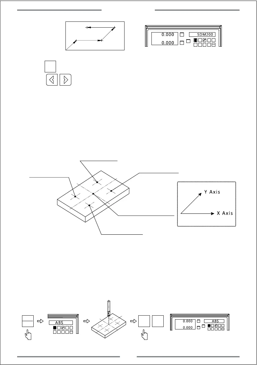
1. Zeroing in place
Set the zero point of work-piece in ABS mode.Move the table to each
machining point,then switch the DRO to be SDM mode and zero the value of
current position.
Step 1,Set the zero point of work-piece in ABS mode.
1 32
-
+
CLS Arc
sin
TOOL
ABS
X0
Y0
X
1 32
-
+
CLS Arc
sin
TOOL
0.000 ABS
X0 Y0
0.000
Switch to ABS
Move the table to the zero point of work-piece
Zero the value of the zero
point of work-piece
ABS
INC
SDM
Basic Function
18
 Loading...