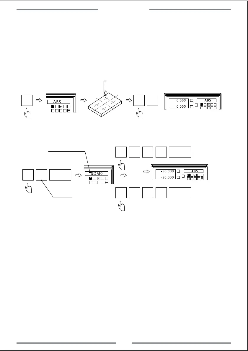
2. Input the number of SDM auxiliary coordinate
Once the zero point of work-piece has been set in ABS mode,move the table to
the zero point.Then input all SDM coordinate at this point
Step 1, Set the zero point of work-piece in ABS mode.
1 32
-
+
CLS
Arc
sin
TOOL
ABS
X0
Y0
X
1 32
-
+
CLS Arc
sin
TOOL
0.000 ABS
X0 Y0
0.000
Switch to ABS
Move the table to the zero point of work-piece
Zero the value of zero point
Step 2, Set the zero point of SDM
SDM
0
NT
1 32
-
+
CLS Arc
sin
TOOL
SDM0
Enter SDM0
X0
Y0
X
1 32
-
+
CLS
Arc
sin
TOOL
-50.000 ABS
Same operation of SDM1,SDM2,SDM3.....SDM199.
X
±
5
0
NT
Y
±
5
0
NT
(0-199)
-50.000
(SDM0-SDM199)
Complete the setting of SDM0
Note:When input the SDM coordinate,we have to do the inversion of positive
and negative.Because the SDM coordinate points on drawing are taking ABS
zero point as reference.In practice they are taking SDM0 as reference.When
inputting,it is parallel to take the ABS zero point by different SDM coordinate.
Note: Quick set of SDM coordinate
ABS
INC
he DRO provides 200 sets of SDM coordinate.To set one by one is time
costly.If the DRO is under ABS or INC mode,press SDM twice.Then input
coordinate number to set.
Basic Function
20
 Loading...