Do you have a question about the Aiphone GF-BC and is the answer not in the manual?
Covers general prohibitions, electrical safety measures, and wiring rules for system installation.
Advises against installing in extreme temperatures, moisture, or vibration prone areas to prevent malfunction.
Specifies indoor use for most equipment and notes system inoperability during power outages.
Provides guidelines for wiring proximity to AC lines and managing radio frequency interference.
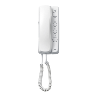
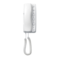
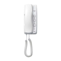
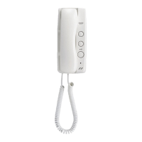
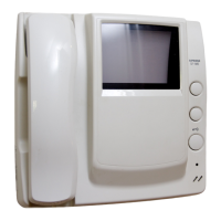
Lists components for apartment stations, including the GF-1D and optional doorbell button.
Details the GF-BC control unit and compatible power supplies like PS-24ME.
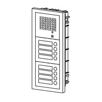
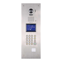
Describes entrance station parts: front frames, panels, modules, and back boxes.
Instructions for assembling modules into the front frame and connecting them with wires.
Details how to connect modules in a daisy-chained manner using plug-in connectors.
Configuration of DIP switches (SET switches) on the GF-DA Speech Module for entrance stations.
Adjusting the door release timer duration from momentary to 20 seconds.
Steps for connecting wires, mounting brackets, and attaching front frames to back boxes.
Illustrates the wiring connections between apartment stations, the control unit, and power supply.
Wiring for controlling external lights using the MAW-B relay.
Guidance on mounting the GF-BC unit and how to reset the system breaker.
Explains the junction point for distributing multiple bus lines to apartment stations.
Instructions on how to adjust the call tone volume or turn it off.
Steps for mounting the apartment station chassis onto an electrical box.
Pressing the PROGRAM switch on the GF-DA Speech Module to enter programming mode.
Steps for lifting handset and pressing call buttons to assign apartment stations.
Procedure for clearing and reprogramming a station if an incorrect setting is made.
Specifies the operating temperature limits for GF entrance station, GF-BC, and GF-1D units.
Recommendations for protecting the entrance station from weather and filling in name plates.
Details power source, current consumption, wiring types, distances, and station capacities.
Aiphone's warranty terms for products, covering defects in material and workmanship for one year.
The Aiphone GF System is a two-wire bus apartment intercom designed to facilitate communication between an entrance station and multiple apartment stations within a building. This system provides a secure and convenient way for residents to identify and grant access to visitors, enhancing overall building security and resident peace of mind.
The GF System comprises several key components:
1. Bus Control Unit (GF-BC): This is the central control unit for the entire system, managing communication flow and power distribution. It comes with necessary screws, an installation manual, and a hexagonal wrench for setup.
2. Power Supply (PS-24ME for AC 230V, PS-2410LC for AC 120V, PS-2410LD for AC 230V): These units provide the necessary power to operate the GF System. They include screws, a DIN rail for mounting, a terminal cover, and a fuse for protection.
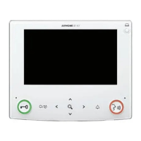
3. Apartment Station (GF-1D): This is the indoor unit installed in each apartment, allowing residents to communicate with visitors at the entrance. Each GF-1D comes with a packet of screws and an operation manual. An optional doorbell button can be connected to the apartment station.
4. Entrance Station: This outdoor unit is installed at the building's entrance and includes several modular components:
*   **Front Frames (GF-2F for 2-module, GF-3F for 3-module):** These frames house the various modules of the entrance station. They come with mounting brackets, screws, and weather stripping for reinforcement. An optional rain hood (GF-H) and connecting wire (GF-C) are available for enhanced weather protection.
*   **Panels:**
    *   **Speech Module & Panel (GF-DA & GF-DP):** The GF-DA is the speech module, handling audio communication, while the GF-DP is the panel itself.
    *   **Call Switch Module & Panel (GF-SW & GF-1~4P):** The GF-SW is the call switch module, which includes a directory card (plate & paper) and a connector. The GF-1P, GF-2P, GF-3P, and GF-4P are call button panels for 1, 2, 3, and 4 calls respectively.
    *   **Blank Panel (GF-BP):** Used to fill unused module slots.
    *   **Address Panel (GF-AP) and Address Module (GF-AD):** These modules allow for displaying apartment numbers or names, with the GF-AD including a directory card (plate & paper) and a connector.
*   **Back Boxes (GF-2B for 2-module, GF-3B for 3-module):** These boxes are mounted in the wall and house the entrance station modules. They come with screws, joint pipes, and a metal plate. It is important to retain these components.
5. Optional Relay (MAW-B): This relay can be used for controlling external lights, such as an entrance light, providing a dry closure contact.
The installation process involves several steps, starting with mounting the back boxes for the entrance station. It is recommended to mount the back box at a height of 150cm (5 feet) up to the box center, allowing a 2mm (1/8 inch) space on each side. The back boxes must be mounted strictly horizontally for best results.
Once the back boxes are in place, the entrance station modules are assembled. Panels of speech and call switch modules are fitted into the front frame from the back. The modules are then attached to the mounting bracket. Wires are plugged into connectors between the modules, ensuring a daisy-chained connection. Connecting wires are passed through joint pipes (pre-opened) and plugged into the appropriate connectors. For optimal drainage, wires should always be run under the plastic cover.
The speech module (GF-DA) is typically located in the middle row of the entrance station. An 80cm (3-1/8 inch) connecting wire (GF-C) is passed through the joint pipes in advance for this purpose.
For the bus control unit and power supply, mounting can be done using screws or by utilizing a DIN rail. A W-DIN11 DIN rail is available from Aiphone for the GF-BC if a DIN rail is not provided.
The apartment station (GF-1D) is mounted on a wall, ideally at a height of 150cm (5 feet) from the floor. Installation involves loosening a screw on the front case, lifting it off the chassis, mounting the chassis on an electrical box, connecting incoming wires to the terminal block, and then remounting the front case. Care should be taken to keep wires away from the PC board section to avoid pinching.
The GF System utilizes a two-wire common bus for communication between the GF-BC, entrance station(s), and apartment stations. Wiring should be performed by qualified personnel. It is crucial to connect the power source only to the specified terminals (+,-) to prevent fire or damage. The equipment must not be exposed to water or other liquids, and AC outlets should be kept away from moisture and dust.
During wiring, the power supply should be unplugged to avoid electrical shock. All wiring should be kept at least 30cm (1 foot) away from AC100-240V wiring, fluorescent lighting, or dimmer switches. If proximity is unavoidable, AC wiring should cross at a 90-degree angle.
The system supports multiple bus lines, with a maximum capacity of 50 apartment stations per bus line and 3 entrance stations per bus line. The total system capacity is 150 apartment stations and 5 GF-DA entrance stations.
After installation and wiring, the system needs to be set up and programmed.
Entrance Station Settings: DIP switches on the speech module (GF-DA) are used to set the entrance station number (1-5). All entrance stations will malfunction if these switches are set incorrectly. The door release timer can be adjusted from 0.5 seconds to 20 seconds, or set to momentary activation. The unit is shipped in the "#1" position and "Momentary" door release setting.
Programming the System:
Correcting Wrong Settings: If an apartment station is incorrectly programmed, lift its handset and keep pressing a call button on the entrance station until a continuous tone is heard. This clears the programming for that call button. For two-station apartments, clearing a call button cancels programming for both stations, requiring individual reprogramming.
The GF Entrance station is weather-resistant, but for best results, it should be protected from direct weather conditions. Installing a rain hood (GF-H) is recommended. The equipment, except the entrance station, is designed for indoor use only.
The system is not operable during a power failure. In areas with nearby broadcasting station antennas, the intercom system may be affected by radio frequency interference.
Avoid installing the unit in areas with high or extreme cold temperatures (under direct sunlight, near temperature-varying equipment, in front of air conditioners, inside refrigerated areas), places subject to moisture or humidity extremes, or places subject to environmental conditions such as oil, dust, chemicals, salt, constant vibration, or impact, as these can cause system malfunction.
| Brand | Aiphone |
|---|---|
| Model | GF-BC |
| Category | Intercom System |
| Language | English |