Mounting Location
Guidelines
CAUTION: Do not mount in line with or near water intake or
discharge openings or behind strakes, struts, fittings, or hull
irregularities that will disturb the water flow.
CAUTION: Do not mount the sensor where the boat may be
supported during trailering, launching, hauling, or storage to avoid
damaging the transducer’s face.
• The water flowing under the hull must be smooth with a
minimum of bubbles and turbulence (especially at high speeds).
• The transducer must be continuously immersed in water.
• The transducer beam must be unobstructed by the keel or
propeller shaft(s).
• Choose a location away from interference caused by power and
radiation sources such as: the propeller(s) and shaft(s), other
machinery, other echosounders, and other cables. The lower
the noise level, the higher the echosounder gain setting that
can be used.
• Choose an accessible spot inside the vessel with adequate
space for the height of the stem and tightening the nuts.
• Choose a location with a minimal deadrise angle.
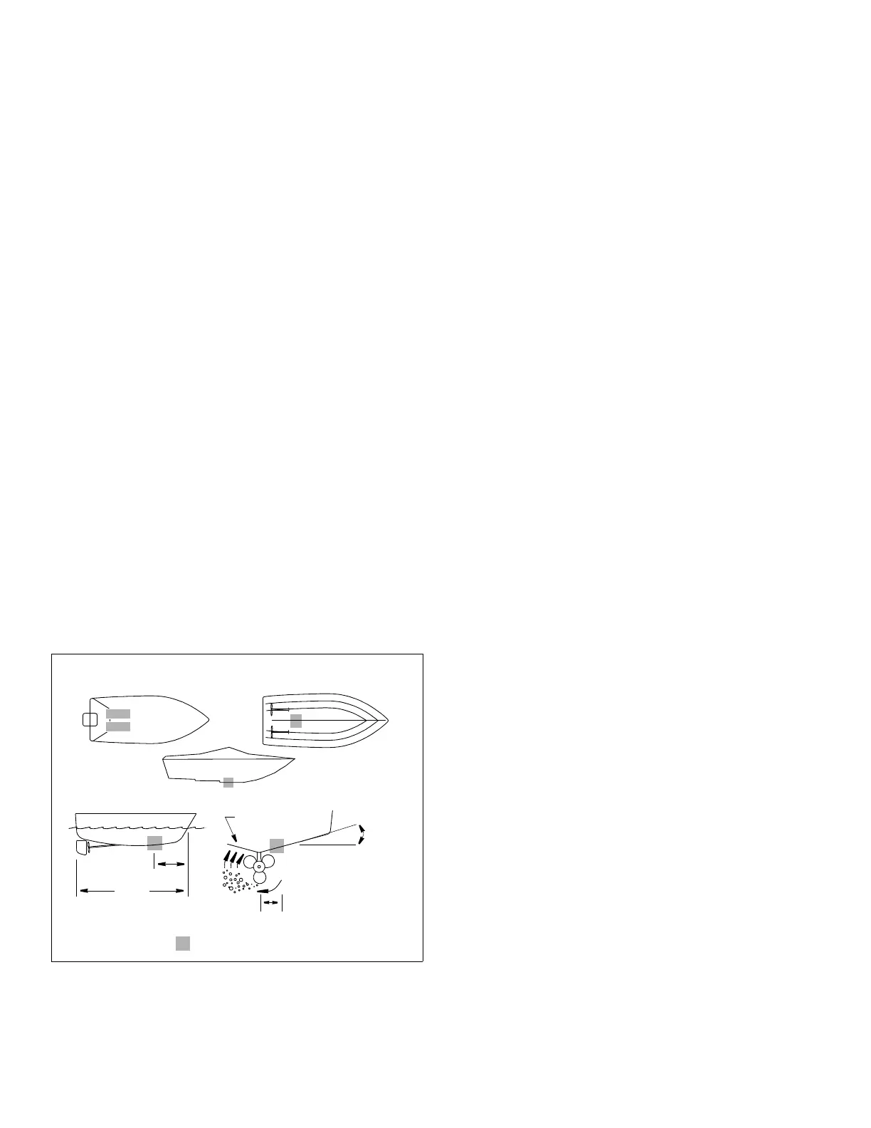
Boat Types (Figure 1)
• Planing hull powerboat—Mount well aft near the centerline
and well inboard of the first set of lifting strakes to insure that it
is in contact with the water at high speeds. The starboard side
of the hull where the propeller blades are moving downward is
preferred.
Outboard and I/O—Mount just forward and to the side of the engine(s).
Inboard—Mount well ahead of the propeller(s) and shaft(s).
Stepped hull—Mount just ahead of the first step.
• Displacement hull powerboat—Locate 1/3 of the way along
the LWL and 150–300mm (6–12") off the centerline. The
starboard side of the hull where the propeller blades are moving
downward is preferred.
2
deadrise
slope of hull
parallel to
displacement hull
pressure waves
1/3
(6-12")
150-300mm
LWL
(Load Waterline Length)
angle
waterline
inboard
stepped hull
outboard
Figure 1.
Copyright © 2010 - 2018 Airmar Technology Corp.
and I/O
planing hulls
Best location for transducer
Tools & Materials
Safety glasses
Dust mask
Ear protection
Angle finder (installation with fairing)
Band saw (installation with fairing)
Block of wood (installation with fairing) min. 4" x 4" x 18"
Screws (4) (installation with fairing) No. 8
Screwdrivers
Rasp or power tool (installation with fairing)
Electric drill
Drill bits and hole saws:
Pilot hole 3mm or 1/8"
Transducer stem 25mm or 1"
Anti-rotation studs
in solid fiberglass or wood hull 9mm or 11/32"
Anti-rotation studs in metal hull 10 mm or 3/8"
Sandpaper
Mild household detergent or weak solvent (such as alcohol)
File (installation in metal hull)
Marine sealant (suitable for below waterline)
Slip-joint pliers
Grommet(s) (some installations)
Cable ties
Water-based anti-fouling paint (mandatory in salt water)
Installation in a cored fiberglass hull: (see page 6)
Drill bits and hole saws for hull interior:
Transducer stem 38mm or 1-1/2"
Anti-rotation studs 19mm or 3/4"
Cylinder, wax, tape, and casting epoxy
 Loading...