138 AS-D+—AS-P Series Instruction Manual
AirSep Corporation
6. Turn the stem (4) so that the valve is fully closed.
Remove body seals (6) and seats (5). Body seals may be
tightly compressed in their grooves. Use extreme care
when prying them out. Damage such as scratches to the
bottom of the groove will cause leaks. If the seats are not
easily removed, gently tap the ball (3) with a piece of
wood or other soft material.
7. Remove the ball (3).
8. Remove the lower stem nut (16) and the compression
ring (21).
9. Press the stem (4) from the top into the valve body (1)
and remove it through the end of the body.
10. Carefully pry out and discard the old stem seals (8), the
stem bearings (24), and the secondary stem seal (7),
being careful not to damage the bearing surfaces.
4.3 Assembly
The following instructions are for in-line assembly. For bench
assembly, which may be more convenient, follow a similar
sequence by holding the valve in a vise by one end cap. Use
care not to cut or scratch the seats, seals or sealing surface.
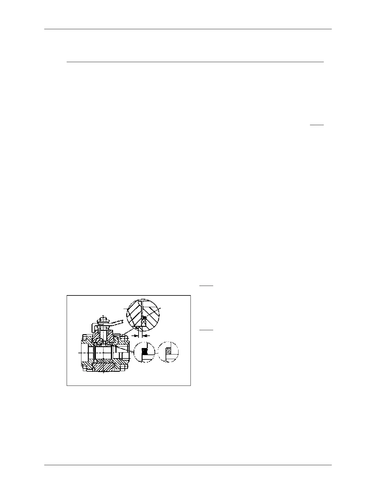
1. With the valve swung to the out-of-line position, insert
from the inside of the body a stem bearing (24), a sec-
ondary stem seal (7), then another stem bearing (24)
into the stem bore. For non-Fire-Tested valves use one
stem bearing (24). (See Figure 3 and parts list.)
2. Insert the stem (4) horizontally into the body bore (thread-
ed end rst). The blade at the ball end of the stem must
be vertical (see Figure 2A and 2B). Guide the stem into
the stem hole being careful not to scratch the bearings.
3. Holding the stem in place from the bottom, install two
stem seals (8), a compression ring (21) from the outside and
thread on one stem nut (16) until the stem starts to turn.
4. Place a wrench through the body on the bottom stem
blade to hold the stem stationary. Place another wrench
on the stem nut and turn the nut down until the seals
are bottomed and the stem comes snugly into place,
applying the torque shown in (Table 2).
5. Align the stem blade with the ball slot. Insert the ball (3),
and rotate the stem (4) to the ball closed position.
6. Working at either end of the body (1), place a seat (5)
into the body. Fit it snugly against the closed ball. NOTE:
The sealing surface of the seat is toward the ball (See
Figure 4).
7. Place a body seal (6) into the machined sealing groove
of the end caps (2) (see Figure 3). Be certain the groove
and seal are clean.
8. Repeat instructions 6 and 7 for assembly at the opposite
end.
9. Turn the stem to the full ball open position.
10. Swing the entire body assembly back into the properly
aligned and interlock position between the end caps,
being careful not to scratch the body seals. Caps may
have to be spread slightly to accept the body.
11. Close the valve.
12. Bolt the valve together with lubricated body bolts (52)
and nuts (53). Tighten these bolts evenly and alternate-
ly. (See Table 1 for the torques and lubricant.)
13. Attach the handle (17), the Shakeproof Washer (19) and
secure them with the stem nut (16) (See Table 2 for
torques).
5. REPAIR KITS
NOTE: FIRE-TESTED repair kits include two seats (5), two
stem seals (8), two stem bearings (24), a secondary seal
(7 and two 316 stainless steel/graphite body seals (6). The
body seals are suitable for valves with carbon steel or 316
stainless trim. Consult the factory for replacement parts of
valves with trim other than carbon or stainless steel, and for
seat material not listed or for special services.
NOTE: NON-FIRE-TESTED repair kits include two seats
(5), one stem bearing (24) and two body seals (6). The
body seals are suitable for valves with carbon steel or 316
stainless trim.
Figure 3
Surface A
Surface A
1/16” (1.6 mm)
Interlock
non fire-testedfire-tested
IMO 3/18
IMO-202 EN 5