W
William YoungAug 15, 2025
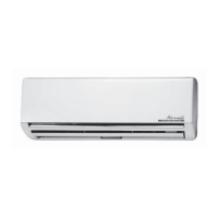
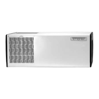
What to do if my Airwell VAR 9 indoor unit is leaking water?
- JJessica MillerAug 15, 2025
If you notice water leaking from the indoor unit of your Airwell Air Conditioner, the most likely cause is a blocked drainage tube. Inspect the drainage tube and clear any obstructions.