OG-UDC 3G-SDI Up, Down, Cross-Converter v1.0 6 www.aja.com
I/O Connections
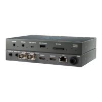
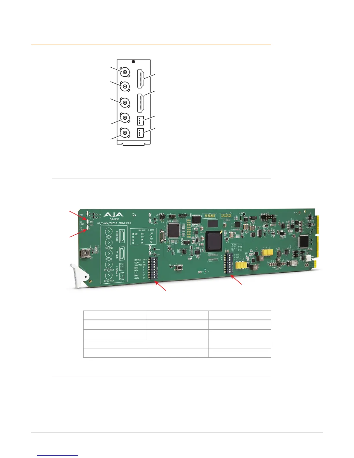
Figure 2. I/O Connections for the OG-UDC
SDI Input
BNC (J1)
Analog Audio
Output L
Analog Audio
Output R
HDMI Output
(inactive)
(inactive)
(inactive)
SDI Output
BNC (J2)
Reference
Input
BNC (J3)
Each 3-pin analog audio connector carries one channel of analog audio output.
Signal Indicators on the OG-UDC Card
Located at the upper front area of the OG-UDC card, the HD Lock and SD Lock
LEDs work in combination to indicate the type of signal detected.
Figure 3. Indicator LEDs and DIP Switch Locations on Card
SD Lock LED
Reference
DIP Switch
General
DIP Switch
Signal Detected HD Lock Light SD Lock Light
No Signal O O
SD Signal O On
HD Signal On O
3G Signal On On
Signal Indicators in the DashBoard Control System
When the signal is either not present or is not locked, the DashBoard Control
System shows both a red Card State alarm and a red Signal State alarm under the
Status tab. Additionally, the SDI Signal Type is shown as "No Signal."
 Loading...