r
U
ADJUSTMENT
OF TAPE
TRANSPORT
UNIT
1. ADJUSTMENT OF
PINCII
WIIEEL
It is imporlant that the piich
wheel shaft i5
kept nr
complcte alignmentwith
the capstan shaft.
A properpinch
wheel
pressur€
is bctween
1.000 and I,150 grahs
whcn the
unit is ope.ated
at the tapc spccd of7-t6
ips. Any devia'
tion
from this specificalion
will result in wow and
flutter.
Check
I'in.h
wheel pre"su,. bv r
.1-.ring
'cale
at.d.
if
r,ecesar
y.
ad
ju"r
rhe pin, h
whpFl
load 5t.inB.
2, ADJUSTMENT OF
TAKE.UP IDLER WHEEL
The
take-up ;dlm wheel
must
be
kcpt in complete align-
ment ltith thc takc-up reel shaft.
Whcn the unit
is set in
fast forward condition,
thc idler
whe€l will contact to the
upper knu.led
wheel
of
the takc-up reel shaft
assembly.
and it
will
contact
to thc lower kn urled
whccl du.ing record
or
play modc. Adjust idlerwhccl
load spr;ngsoihatlhc
idler
wheel pressurc is kept between 50
and 80 grams.
The
;dler
qh..l
rapidlv
wear.
:f Ihf pre*u,.
b
Px,.ssi\c.
The slippage occurs
if thc prcssu.e
is smallef thaD the
3. ADJUSTMENT
OF
REWIND IDLER
WSEEL
The .c\rind
idler
whccl
must be kcpt in complete
align-
mcnt with thc rewi.d
reel
shaft. The amount
of
pressurc
to the k,,urlcd
motor bushing should be maintained
about
50 gfams during rewidd ope.ation. Adjust both thc idler
load spriog aDd
rewind roller.
4. ADJUSTMENT
OF
INTERMEDIATE WHEDL
Thc
intcrnediatc
wheel
is located between the
rewind
idler
whccl
and thc rubbe. ring vhich is uscd on the uppe.
part
of
the supply
reel shaft assembly. When
the unit is
sct in rewind mode, it will
contact
to thcsc parts sihul-
taneously deliverins torque of
motor. An
adequate
pres-
su.cis50grams. Adjust thc load sp.;ngofthc inrermed;ate
wheel if the
pressure is not sufrc;ent.
5. ADJUSTMENT OF TAKE-UP REEL SIIAI'T
ASSEMBLY
A felt clutch mat.rial is attachcd to the bottom sid€
ol
the
reel
table
basc plat€ so
that reco.ding tapc w;ll not bc
stretched during lhst forwafding operation due
to
excesivc
tension. To check the
amoudt
of friction of this part, plac€
a S'inch reel
with
fecordins
tape wound by 60m/m in
diameter, and gently pull the cnd of tapc upwarcl
using a
spring scale.
Adjust the
conical
sp.ing so that thc amount
of tension at this part will bc kept between
400 to
500
grams. Anoth€r felt
clutch
matoial ;s
attached
to
the
takc-up drive wheel. It is to pfovide proper slipping
opc-
ration
du.ing
record or play modc. The procedu.e
for
checkins friction of
this part
; same as
the foregoing, and
between 120 and 200 grams of frictioD
will provide the
best result.
Adjust the
star-shapcd
spring
jnst
under
the
takc-up dr;ve
whcel.
lvhen
the unit is
set
in rewind
mode,
the
amou.t
of f.iction of this part
will greatly
be
reduced and \viil become I0
to 20 grams.
Check
to scc
rvhether this is satisfactory ;f iot,
readjust the star-shaped
spring
fo. Bfakc, and spring rctainef
washed
accordingly.
lscc
fisure
ll
(al
at
lefo
6. ADJUSTMENT
OF SUPPLY REEL SIIAFT
ASSDMBLY
A felt clutch
matoial is uscd between
the love.
side
of
thc reel table base plate and
the .ewind rubbcr ring
to
protect reco.ding
tape from an excesive
tension \th;le re-
winding operation.
To
check
thc
amount
offriction of
this
pa.t, place onto thc supply reel
table
a 5-inch
rcel with
rcco.ding
tape wound by 60m/m in diameter and
gently
pulL thc cnd of tape upward by a spring
scale. Adjust
thc
conical sp.ing so
that thc amount of
tens;on ;s kept
bctwecn 400and500grams.
Anothc. fclt clutch is attached
to thc re\v;nd
drive
wheel to provide
proper
sl;pping
ope.atioD cluring
reco.d or play mod.. The procedure
for checkn)g
friction of this part is same as
the
foregoing,
and betwe€n 80 and
120
s.ams
of friction will give
the
best
result. Whcn
the
unit
js
set
;n fasi forward modc,
the
amount
of f.;ction will greatly be reduced and
will
become l0 to 20
grans.
Check
to
sce
whether this is proper, if not,
rcadjust coil
spring and spring r€tainer
washc..
{See
figure I I
(b)
at left)
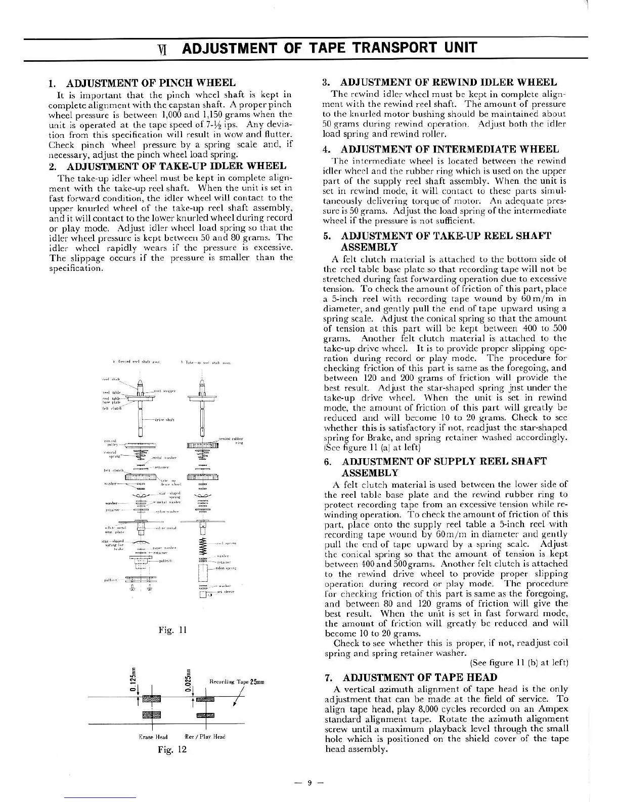
7. ADJUSTMENT
OF TAPE HEAD
A
vertical azimuth
alignment of
tape head is the only
adjustment
that
can
be made at
the field
of service.
To
align tape head, play 8,000 cycles
recordcd on an AmP€x
standard alignment
tape. Rotate
th€
azimuth al;gnment
sc.ew
until a maximum
playback level through the small
hole which
is positioned on the shield cover
of the tape
head assembly.
-9-
..t,
;
Fig.
ll
R(/.Ly Hli
Fig.
12
:ir".
=..".".,..
 Loading...