tll
ADJUSTMENT
OF
AMPLIFIER
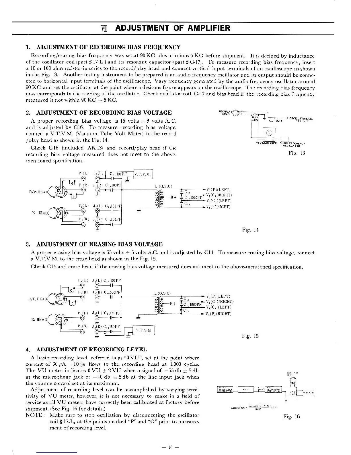
r. ADJUSTMENT OF RECORDING BIAS FREQUENCY
Rccording/crasing bias frcquctrcy
was
set at 90 KC plus or m;nus
5
KC
before sh;pment. It is
decided by inductance
otthc oscillato. coit
lpart *
l7-L,)
and
its resonant
capac;tor
(part
f
C-17). To mcasu.e recordiDg
bias frcquency, insert
a
l0
or
100
ohm
resisto. ;n
scrics
to the .cco.d/play head
and coDnect vertical ;dput te.minals
of an oscillos.ope
as showq
in
the
Fig.
13. ADothcr testirg
instrument
to
be prepared is an audio frcquency
oscillator and
jtsoutput
shouid
be conDe-
cted to hor;zontal input terminals .,f the oscilloscope. Vary frequcncy gene.ated
by
tbe
audio frequency
oscillator around
90 KC, and set the oscillator at the point whe.r a desirous 6gurc appears on the
oscilloscopc.
'fhc
recordins bias
frequcncy
no$' corrcsponds to the reading of the oscillator. Check oscillator coil, C-17
and bias head if the recording
bias frcqucncy
mcasu.ed ; not w;thin 90 KC
+
5 KC.
2, ADJUSTMENT OF RDCORDING BIAS VOLTAGE
A p.oper rccordnrg bias vottagc is 45 volts
+
3 volts A.C.
and is adjusted
by
Cl6.
To measure .eco.ding bias voltage,
coDD€ct
a
V.T.V.M.
(Vacuum
Tube Volt Mete.) to the record
/play
head
as showD
;r the lig. 14.
Check Cl6
(included
AKl3)
and
record/play head if the
recording bias voltage
mcasu.ed
does
not meet to th€
abovc-
mentioned specificatioD.
L1{0,s.c)
Fig. 13
li'
-I
j(PllLEFT]
Hi|mn-!,(c,lEIcHr)
I#ltlri!i
F;g. 14
3. ADJUSTMENT OF
ERASING BIAS
VOLTACE
A prope.
€rasing bias
voltagc is 65 volts
+ 5 volts
A.C.
and is adjusted by Cl4.
To
neasure erasing bias voltage, connect
a V.'[.V.M.
to the
erase
head
as rhown
in the Fig. 15.
Chcck Cl4 and crasc head il thc oasing bias voltage measured
does
not meet to the
above,mentioned spe€ification.
Fig. 15
4.
ADJUSTMENT
OF
RECORDING LEVEL
A
basic
rccording lcvcl, .cfefcd to
as
"oVU",
s€t at
th€ point
where
current of
30lA
+
l0
%
flows to the recording head
at
1,000 cycl€s.
The VU neter indicates oVU
!
2 VU wheD a signal of
-55
db
+
5 db
at the microphone
jack
or
-40db
+
5db at the line input
jack
when
thc volumc control set at its maximum.
Adjustment ot recording level can be accomplishcd by varying
sensi-
tivity of VU metft, however, it is not necesa.y to make in
a
field
of
service as all VU
mete6 have co..ectly been calibrated at
factory befor€
shipment.
(See
lig. l6
for details.)
NOTEi Make sure to stop oscillation by disconnecting the oscillator
coil
|
17-L, at the points marked
"P"
and
"G"
prior to measure,
ment
of
reco.ding lcvct.
i f^-
o;.---r:@*=;;'6d.".0,.-""
#;;;-v'1c'
lRrcHr)
I;':I:::j-:-
v
'
1i,l
l1
LE FT
)
v,(P)(RrcHT)
o-, ^
-,nrl
ll,,n
r
r"
Fig. t6
 Loading...