Do you have a question about the Akai GX-747 dbx and is the answer not in the manual?
Checks insulation resistance after servicing for electrical safety.
Guidelines for safe servicing procedures and part replacement.
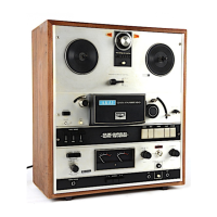
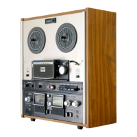
Detailed technical specifications of the GX-747dbx tape deck.
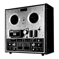
Procedures for unit disassembly and identification of all controls.
Explanation of circuit operations, EE tape, dbx system, and mechanism adjustments.
Covers head, electrical adjustments, coil resistance, and PC board classification.
List of critical parts recommended for stocking for repairs.
Important notes on ordering parts and using the parts list.
Diagrams and parts lists for head, motor, reel, and roller assemblies.
Diagrams and parts lists for various P.C. boards.
Diagrams and parts lists for sub-assemblies and the final unit.
Diagrams illustrating the pin configurations of various integrated circuits.
Overall schematic diagram for the Syscon control system.
Schematic diagram for the audio amplifier circuits.
| Track System | 4-track, 2-channel stereo |
|---|---|
| Reel Size | up to 10.5 inch reel |
| Type | Reel to Reel |
| Heads | 2 x erase |
| Motor | 1 x capstan, 2 x reel |
| Tape Speed | 9.5 cm/s, 19 cm/s |
| Wow and Flutter | 0.03% (19 cm/s) |
| Signal to Noise Ratio | 65dB |
| Input | 1 x line, 1 x microphone |
| Output | 1 x line |
| Dimensions | 440 x 480 x 260 mm |