IX.
ELECTRICAL
ADJUSTMENT
PHOTO
TRANSISTOR
SENSITIVITY
VR3
I
~J
TP3
t
t
CLOCK
FREQUENCY
IFT
I
TPI
~~J
~~~g~ENCY
IFT2
YSCON
PCB
T1009A2570
Fig. 9-2
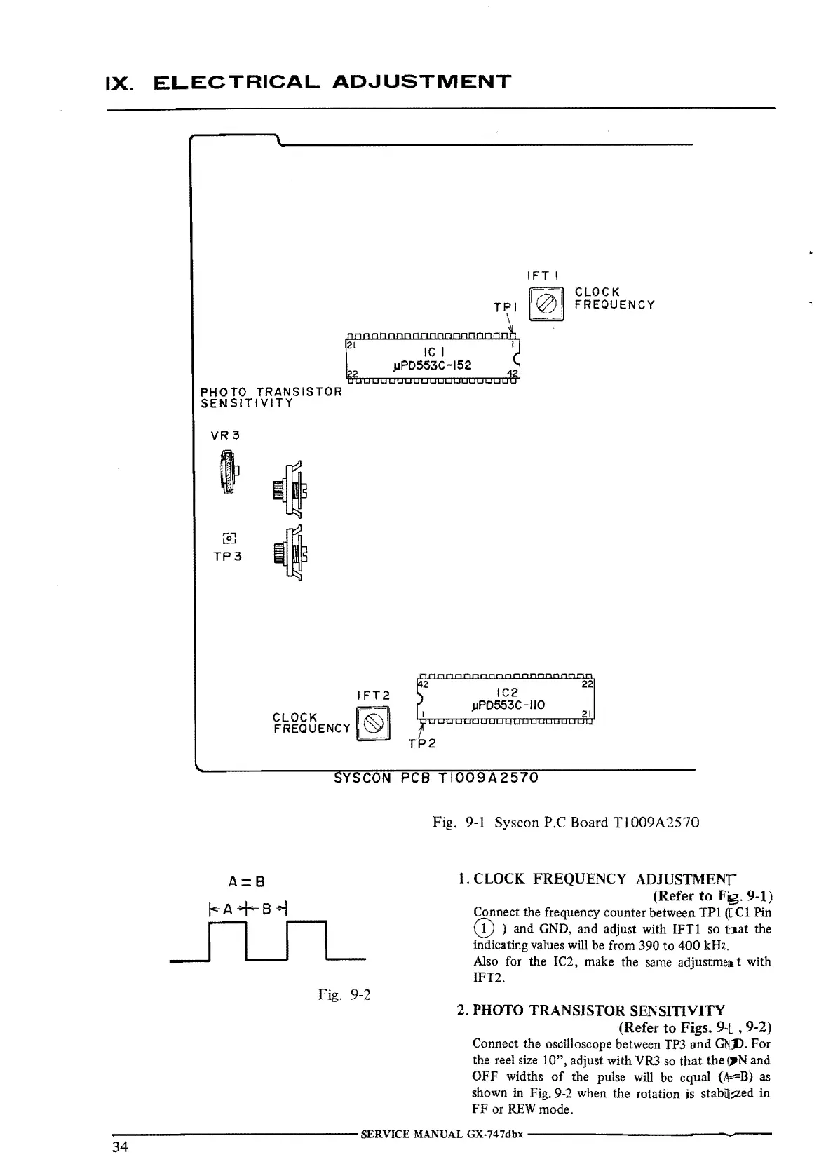
Fig.
9-1
Syscon P.C Board
TI009A2570
1. CLOCK FREQUENCY ADJUSTMENT"
(Refer
to
Fig. 9-1)
Connect the frequency counter between
TPl
([
Cl
Pin
(D
) and GND, and adjust with
IFTI
so tt,.at the
indicating values will
be
from 390 to
400
kHz.
Also for the IC2, make the
same
adjustmell-t with
IFT2.
2.
PHOTO
TRANSISTOR
SENSITIVITY
(Refer to Figs.
9-L
, 9-2)
Connect the oscilloscope between
TP3
and
Gt{D. For
the reel
size
1 O", adjust with VR3
so
that
the
~N
and
OFF widths
of
the pulse
will
be
equal
(A::::=B)
as
shown in Fig. 9-2 when the rotation is stabi]::zed in
FF
or
REW
mode.
--------------SERVICE
MANUAL GX-747dbx
---------------
34

 Loading...