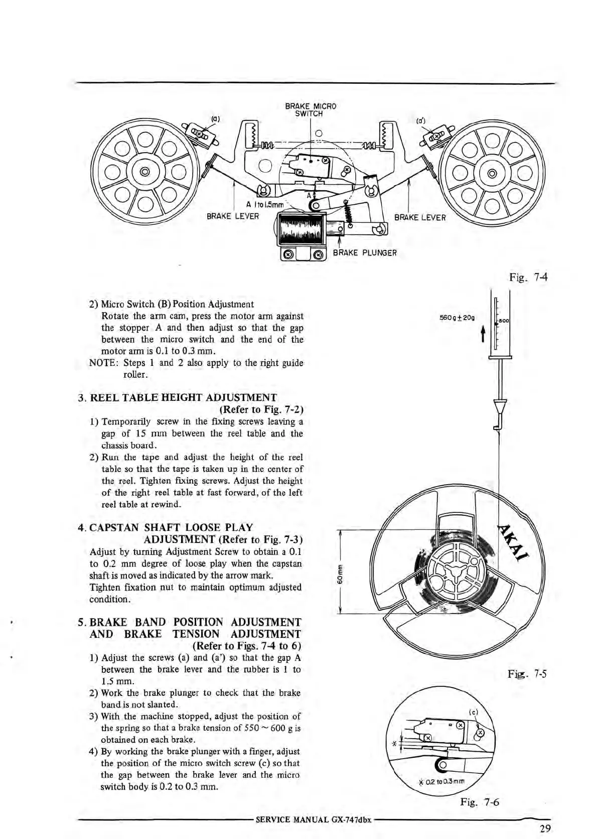
BRAKE MICRO
SWITCH
2) Micro Switch (B) Position Adjustment
Rotate the
arm
cam, press the motor arm against
the stopper A and then adjust
so
that the gap
between
the
micro switch and the end
of
the
motor
arm is 0.1
to
0.3 mm.
NOTE: Steps 1 and 2 also apply to the right guide
roller.
3.
REEL TABLE HEIGHT ADJUSTMENT
(Refer to Fig. 7-2)
1) Temporarily screw in the fixing screws leaving a
gap
of
15
mm
between the reel table and the
chassis board.
2)
Run
the tape and adjust the height
of
the reel
table
so
that
the tape
is
taken up in the center
of
the reel. Tighten fixing screws. Adjust the height
of
the right reel table at fast forward,
of
the left
reel table at rewind.
4. CAPSTAN SHAFT LOOSE PLAY
ADJUSTMENT
(Refer to Fig. 7-3)
Adjust by turning Adjustment Screw to obtain a 0.1
to
0.2 mm degree
of
loose play when the capstan
shaft
is
moved as indicated by the arrow mark.
Tighten fixation
nut
to maintain optimum adjusted
condition.
5. BRAKE BAND POSITION ADJUSTMENT
AND BRAKE TENSION ADJUSTMENT
(Refer to Figs. 7-4 to 6)
1)
Adjust the screws (a) and (a')
so
that the
gap
A
between the brake lever and the rubber is 1 to
1.5mm.
2) Work the brake plunger to check that the brake
band is
not
slanted.
3) With the machine stopped, adjust the position
of
the spring so that a brake tension
of
550 ~ 600 g
is
obtained on each brake.
4)
By
working the brake plunger with a finger, adjust
the position
of
the micro switch screw (c)
so
that
the gap between the brake lever and the micro
switch body
is
0.2 to 0.3 mm.
E
E
0
<D
560g±20g
Fig. 7-4
Fig.
7-5
Fig. 7-6
---------------SERVICE
MANUAL
GX-747dbx
---------------
29

 Loading...