PINCH
ROLLER
PLUNGER
~o
CH
ROLLER
Fig. 7-8
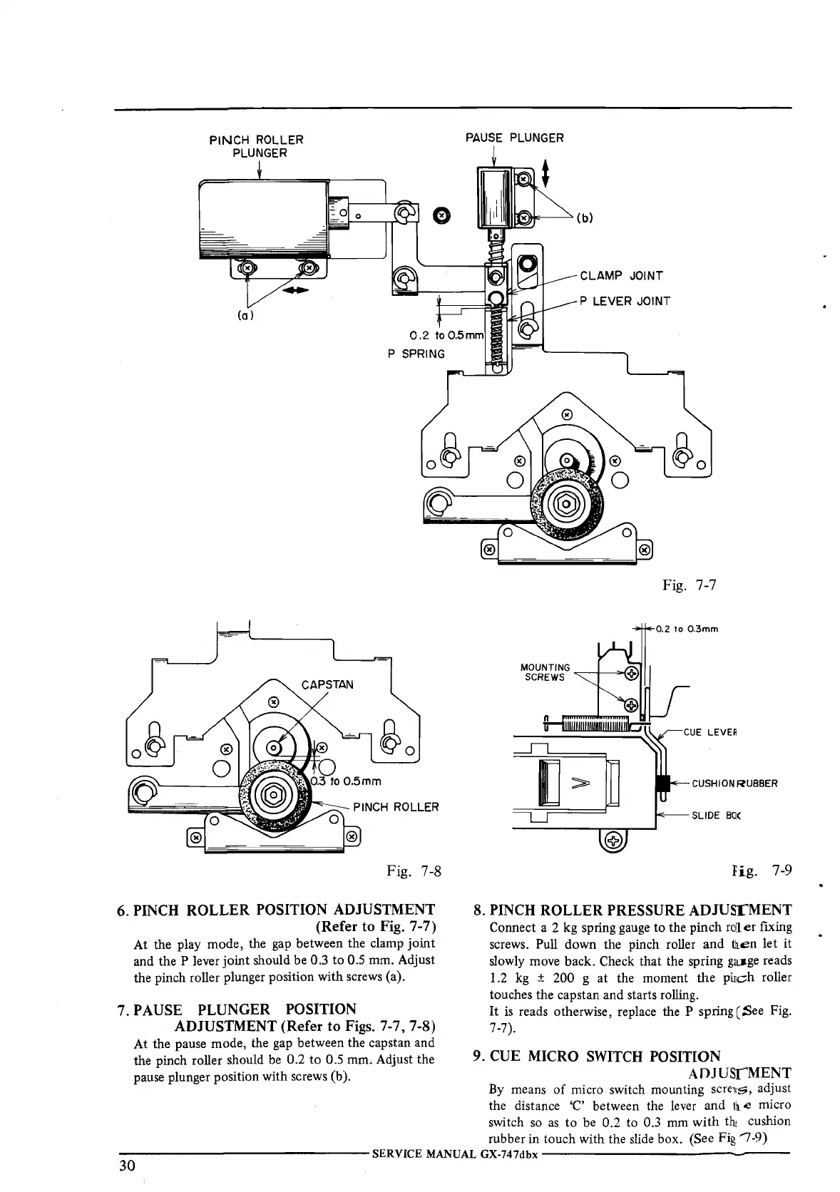
6. PINCH ROLLER POSITION ADJUSTMENT
(Refer
to
Fig. 7-7)
At the play mode, the gap between the clamp joint
and the P lever joint should be 0.3
to
0.5 mm. Adjust
the pinch roller plunger position with screws (a).
7. PAUSE PLUNGER POSITION
ADJUSTMENT (Refer to Figs.
7-7, 7-8)
At the pause mode, the gap between the capstan and
the pinch roller should
be
0.2
to
0.5 mm. Adjust the
pause plunger position with screws (b ).
PAUSE
PLUNGER
CLAMP JOINT
P LEVER JOINT
Fig. 7-7
0.2 to 0.3mm
CUSHION RUBBER
SLIDE
BO(
Fig.
7-9
8. PINCH ROLLER PRESSURE ADJUSrMENT
Connect a 2 kg spring gauge
to
the pinch
roll
er
fixing
screws. Pull down the pinch roller and
tli.en let it
slowly move back. Check that the spring
ga~ge
reads
1.2
kg
± 200 g at the moment
the
piJich roller
touches the capstan and starts rolling.
It
is
reads otherwise, replace the P spring ( See Fig.
7-7).
9. CUE MICRO
SWITCH
POSITION
ADJUSrMENT
By means
of
micro switch mounting scretsi, adjust
the distance 'C' between the lever and
1li
e micro
switch
so
as
to
be 0.2 to 0.3 mm
with
thi
cushion
rubber in touch with the slide box. (See
Fig '7-9)
---------------SERVICE
MANUAL
GX-747dbx
---------------
30

 Loading...