EasyManua.ls Logo

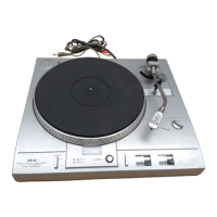
Akai AP-D40

Akai AP-D40
59 pages
To Next Page IconTo Next Page
To Previous Page IconTo Previous Page
Loading...
Teer
Supply
terminal
giving
a
high
level
of
output
voltage
for
APC-OUT.
Terminal
connecting
2.7
MHz
X’tal
at
FG
=
180
pulses/1
revolution.
33
IN
4
Terminal
selecting
the
speed,
has
built-in
pulll
up
resistors
becoming
active
at
45
IN
5
“L”
level.
33/45
OUT
a
ae
Becomes
“L”
level
when
set
to
33-1/3
rpm.
Strobe
signal
output
terminal
and
duty
is
1/10.
Output
frequency
is
the
same
as
that
of
the
input
pulse
FG-IN
from
the
motor
when
the
speed
is
accurate.
Input
signal
terminal
for
minute
adjustment.
32
step
speed
control
possible
in
steps
of
0.2%
by
5
bit
binary
code.
Test
point
at
APC
sampling
signal
output
terminal.
GND
terminal.
Supply
terminal
12v*1¥
Terminal
for
condenser
connection
to
generate
APC
circuit
saw
waves.
ee
Terminal
for
condenser
correction
to
store
APC
sampling
voltage.
Terminal
to
control
APC
circuit
saw
wave
tilt.
APC
output
voltage
terminal.
AFC-OUT
AFC
output
voltage
terminal.
VoGc-F
21
Supply
terminal
giving
a
high
level
of
output
voltage
for
AFC-OUT.
FC,
22
Terminal
for
condenser
connection
to
generate
AFC
circuit
saw
waves.
FC,
23
Terminal
for
condenser
connection
to
store
AFC
sampling
voltage.
24
Terminal
to
control
AFC
circuit
saw
wave
tilt.
Test
point
at
AFC
sampling
signal
output
terminal
J
i
N
N
WN
FG-IN
26
Terminal
inputting
pulses
to
correspond
to
motor
speed.
LOCK
©
7
Outputs
“L”
level
when
the
motor
is
PLL
locked.
Inside
is
an
open
in
MOS
FET
and
the
LEDs
can
be
directly
driven.
Supply
terminal
SV
+
0.5V
<
~)
iw]
;
oo
vn
Chart-1
17

Related product manuals