Do you have a question about the Akai AP-206 and is the answer not in the manual?
Technical specifications for the AP-206/C model, covering turntable, motor, speed, and dimensions.
Technical specifications for the AP-306/C model, including drive system, rumble, and power requirements.
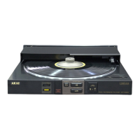
Identification and description of control elements on the AP-206/C model, including speed selectors and pitch controls.
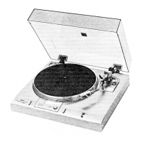
Overview of the control interface for the AP-306/C model, featuring speed selector and quartz lock switches.
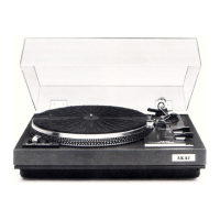
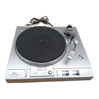
Detailed identification of principal components for the AP-206/C model in top and bottom views.
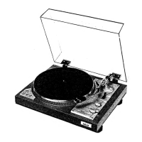
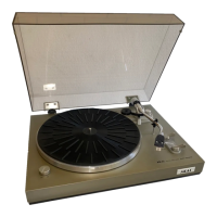
Location and labeling of main parts for the AP-306/C model, illustrated with top and bottom views.
Schematic block diagram illustrating the operational flow and components of the AP-206/C turntable.
Block diagram detailing the internal circuitry and signal paths for the AP-306/C turntable model.
General description of the direct drive and PLL circuits, including the role of the strobe circuit.
Explanation of the servo circuit's function, detailing operation with Quartz Lock switch ON and OFF for speed control.
Description of the strobe light circuit's function, how it synchronizes with the crystal oscillator for speed indication.
Procedure for adjusting stylus pressure, including zero balance and setting the pressure scale ring.
Instructions for adjusting the cartridge overhang using the indicator groove on the turntable mat.
Method for adjusting the sleeve position to set the anti-skating feature, referencing figure 13.
Steps to adjust the PU plate to ensure proper actuation of the microswitch for the automatic mechanism.
Guidance on adjusting the tone arm lifter height to ensure correct stylus positioning relative to the record.
Procedure for setting the automatic return point of the tone arm, specifying clockwise/counter-clockwise adjustments.
Procedures for adjusting off-set voltage (VR4, VR5) and duty ratio (VR1) on the direct drive PC board.
Adjustments for the PLL PC board, including oscillation frequency (VC1) and phase angle (VR1).
Procedure for adjusting torque difference (VR6) using an AC voltmeter for balanced motor output.
Steps to adjust speed settings (VR2, VR3) for 33-1/3 and 45 RPM using strobe markings.
Table listing various PC boards, their identification numbers, and the models they are utilized in.
Schematic diagrams showing the layout and components of the Direct Drive and PLL P.C. boards.
| Motor | DC servo motor |
|---|---|
| Speeds | 33 1/3, 45 rpm |
| Wow and Flutter | 0.03% WRMS |
| Tonearm Effective Length | 220 mm |
| Overhang | 15 mm |
| Platter | Aluminum Die-Cast |
| Tonearm Type | Static Balance Type |