,
..
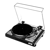
~TONE ARM
t
TONE ARM LlFTER
ABOUT Bmmrl
~-'lr°~
1----
Fig. 14
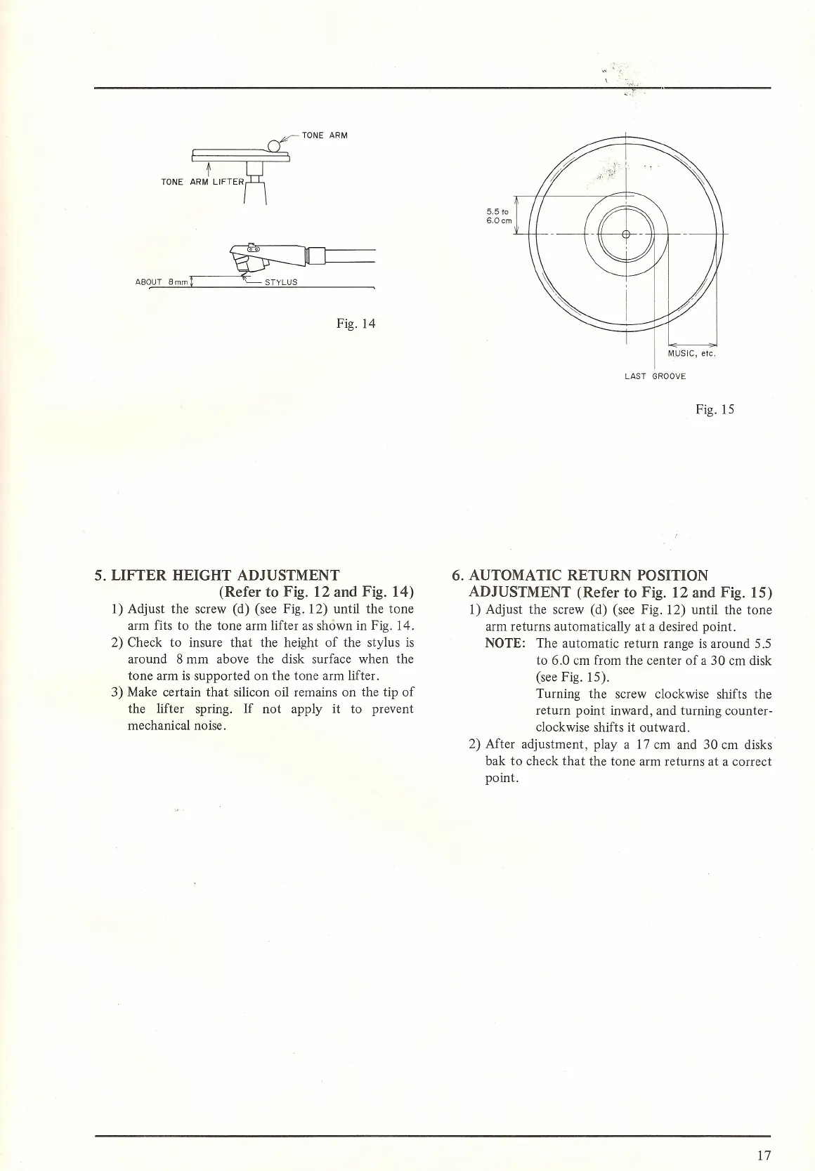
5. LIFTER HEIGHT ADJUSTMENT
(Refer to Fig. 12 and Fig. 14)
1) Adjust the screw (d) (see Fig. 12) until the tone
arm fits to the tone arm lifter as shown in Fig. 14.
2) Check to insure that the height of the stylus is
around 8 mm above the disk surface when the
tone arm is supported on the tone arm lifter.
3) Make certain that silicon oil remains on the tip of
the lifter spring. If not apply it to prevent
mechanical noise.
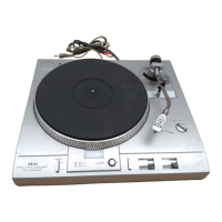
5.5
to
6,Ocm
M,USIC, etc.
LAST GROOVE
Fig. 15
6. AUTOMATIC RETURN POSITION
ADJUSTMENT (Refer to Fig. 12 and Fig. 15)
1) Adjust the screw (d) (see Fig. 12) until the tone
arm returns automatically at a desired point.
NOTE: The automatic return range is around 5.5
to 6.0 cm from the center of a 30 cm disk
(see Fig. 15).
Turning the screw clockwise shifts the
return point inward, and turning counter-
clockwise shifts it outward.
2) After adjustment, play a 17 cm and 30 cm disks
bak to check that the tone arm returns at a correct
point.
17
 Loading...