69
VIDEO DOOR ENTRY INSTALLATIONS
6+N+COAXIAL SYSTEM
STANDARD INSTALLATION
6+N+COAXIAL SYSTEM
Standard wiring diagram for electronic video door entry
installations in buildings with a single entry point.
Operation
When one of the push-buttons of the entrance panel is
pressed, the audio unit activates the video unit (connector
19) and generates an electronic call signal (terminal 7)
which is carried by the call wire to the corresponding moni-
tor (terminal 5). The loudspeaker of the handset of the moni-
tor emits a warning sound, informing the house of the inco-
ming call. At the same time, the visitor hears a sound, pro-
duced by the loudspeaker of the audio unit, which confirms
that the call to the house has been made. The video unit swit-
ches on and captures the image of the visitor and sends the
video signal to the monitors (V1, M).
The monitor is activated and connected to the power
supply terminals (terminals -,+) when it receives the call. The
monitor then sends the supply voltage (terminals V1, M) to
the top output of the tap-off to which it is connected, allo-
wing it to receive the video signal of the video unit (termi-
nals V1, M) and to show the image of the visitor.
The monitor is also connected to the common wire (2) and
to the lock release wire (1). If the handset is picked up, the
audio wires (3 and 4) of the monitor are connected to the
entrance panel, establishing conversation with the visitor.
When the lock release button of the monitor is pressed, the
audio unit detects the closing of the lock release circuit (ter-
minal 1 to ground). The audio unit then sends an alternate
voltage (terminals 11 and 12) to the electric lock, permitting
the opening of the door.
All the signals are closed through the common wire (ter-
minal 2) of the monitor and of the audio unit.
Time settings established by the audio unit:
Time limit to answer the call 30 seconds.
Auto switch-on
When the auto switch-on button is depressed, and
always providing that another monitor is not active, the
monitor is activated and presents the same characteristics
as if a call has been received from the entrance panel.
Time settings for the audio unit 30 seconds or until the
handset is replaced.
During the time settings (answer, conversation and auto
switch-on) all the other monitors are inactive.
230 V
V
5
5
2
2
ABR-001
2
1
2
ALA-040
230 V
V
ALM-040
2
2
COAX
MDN-041
4+N
MPS-004
DIV-024
MVB-001
+
SCM-010
22
SECTION TABLE
Up to 100 m
1,1 mm
0,6 mm
0,25 mm
2
AWG
17
1 mm
2
COAXIAL 75 Ω
MATERIAL REQUIRED
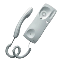
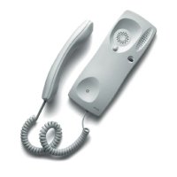
MPS-/MPD-
MDN-041
SCM-010
DIV-024
ABR-001
ALM-040
ALA-040
MVB-0019630000
9630002
9730031
9670043
9730000
9620011
9620003
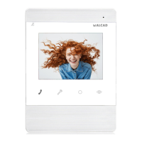
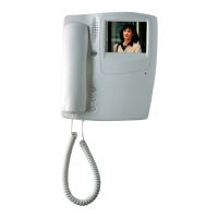
Analogic B/W video door entry monitor
Monitor connection bracket
Video tap-off coaxial cable 4 tap outputs
Push-button module (depending on characteristics of the installation)
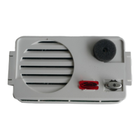
Module with audio unit and video unit TCB-010
Standard electric lock (other models available)
Power supply AC-DC
Power supply AC
Time for conversation 60 seconds or until the handset is
replaced
 Loading...