80
INSTALLATION WITH THREE POINTS OF ENTRY
6+N+COAXIAL SYSTEM
Standard wiring diagram for electronic video door entry
installations in building with three entry points.
Operation
One of the three entrance panels must be defined as the
main panel. When the auto switch-on system is activated
from the monitor, communication (both visual and audio) is
established with this main panel.
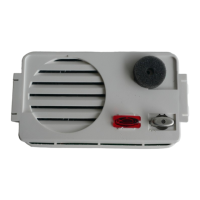
When one of the push-buttons on one of the entrance
panels is pressed, the audio unit activates the video unit
(connector 19) and generates an electronic call signal (ter-
minal 7) which is sent by the call wire to the corresponding
monitor (terminal 5). The loudspeaker of the handset of the
monitor emits a warning sound, informing the house of the
incoming call. At the same time, the visitor hears a sound,
produced by the loudspeaker of the audio unit, which con-
firms that the call to the house has been made. The video
unit switches on and captures the image of the visitor and
sends the video signal to the monitors (M, V1). Normally,
the monitors are connected to one of the two video units by
default. If the other video unit is used by the visitor the video
signal is sent through the default unit (terminals M, V2) and
from there the signal is sent to the monitors (terminals M,
V1). In addition, the audio unit generates a control signal
(terminal 17) which deactivates the other entrance panels.
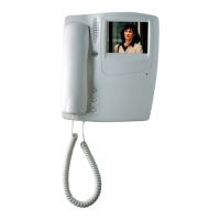
The monitor is activated and connected to the power
supply terminals (terminals -,+) when it receives the call. The
monitor then sends the feed voltage (terminals V1, M) to the
top output of the tap-off to which it is connected, allowing it
to receive the video signal of the video unit (terminals V1,
M) and to show the image of the visitor.
Independently to the entrance panel from which the call is
made, the monitor is also connected to the common wire (2)
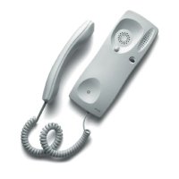
and to the lock release wire (1). If the handset is picked up
the audio wires (3 and 4) of the monitor are connected to
the entrance panel, establishing conversation with the
visitor. When the lock release button of the monitor is
pressed, the audio unit detects the closing of the lock
release circuit (terminal 1 to ground). The audio unit
then sends an alternate voltage (terminals 11 and 12) to
the electric lock, permitting the opening of the door.
All the signals are closed through the common wire
(terminal 2) of the monitor and of the audio unit.
Time settings established by the audio unit of the
entrance panel from which the call is made:
Time limit to answer the call 30 seconds
Time for conversation 60 seconds or until the handset
is replaced
When either of the two time settings expire the audio
unit eliminates the control signal (17), and all three
entrance panels return to stand-by status.
Auto switch-on
When the auto switch-on button is depressed and
always providing that another monitor is not active, the
monitor is activated and enters into communication with
the entrance panel defined as the main panel. The
audio unit of the main panel does not generate the con-
trol voltage so it is possible to make a call from any of
the panels.
Time settings for the audio unit 30 seconds or until the
handset is replaced.
 Loading...