Do you have a question about the Alcad CAD-704 and is the answer not in the manual?
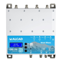
Specifies the number of input ports available on the amplifier.
Enables automatic scanning for channels, simplifying setup and tuning.
Features switchable filters to mitigate interference from cellular bands.
Allows for precise filtering of up to 64 channels using Automatic Gain Control.
Capability to convert a specific number of channels for signal processing.
Provides a display for viewing settings and operational status information.
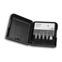
Describes the material used for the amplifier's durable casing.
Avoid extreme temperatures, ensure dry location, mount securely, and maintain ventilation.
Keep away from water, liquids, and open flames to prevent damage or fire.
Use only the supplied power pack to avoid malfunction and voiding warranty.
Details various input ports, display, USB, and output terminals for system integration.
Connect grounding wire and TV aerials to the amplifier's designated inputs.
Instructions on activating the display and entering the programming menu using navigation keys.
Procedure for setting up a password and entering it to access the programming menu.
Details the automatic channel scanning process for UHF and BIII bands, including settings.
Steps to begin manual channel programming by selecting the 'MAN' option.
Configure FM/BI input parameters, including voltage and gain adjustments.
Details configuring the VHF-UHF input, including available channels and gain adjustment.
Explains how to set output voltage and adjust input gain based on input power levels.
Instructions for filtering a single channel or adding one with specific parameters.
Procedure for filtering and converting a single channel to a different frequency.
Process for filtering two adjacent channels simultaneously.
Steps to delete an existing channel filter or conversion from the system.
Details settings for the second VHF-UHF input, including channel availability and filtering.
Describes the configuration options for UHF inputs 3 and 4, including available channels.
Procedure to select and adjust the amplifier's output signal level.
Procedure to select and adjust the output signal slope for optimal signal quality.
Allows selection and configuration of LTE filters (e.g., 4G, 5G) for UHF bands.
Selects the DC voltage setting for inputs, choosing between 12V or 24V.
Procedure for setting up and removing the password protection for menu access.
Sets the minimum threshold for the AUTO-SCAN function within a specified range.
Procedure to reset the amplifier to its original factory settings.
Locates and displays the unique serial number of the product.
Instructions for safely exiting the current configuration or operation.
Downloadable software for PC control, configuration saving, and loading.
Lists hardware and software prerequisites for installing and running the control application.
Details compliance with Radio, Low Voltage, and RoHS directives, indicated by the CE mark.
Product meets stringent screening requirements according to EN 50083-2, quality grade A.
| Category | Amplifier |
|---|---|
| Model | CAD-704 |
| Input Sensitivity | 1V |
| Frequency Response | 20Hz - 20kHz |
| Damping Factor | >100 |
| Dimensions | 430mm x 90mm x 300mm (W x H x D) |