Residential HRV/ERV
24
CAUTION: Turn o power to avoid risk of malfunction.
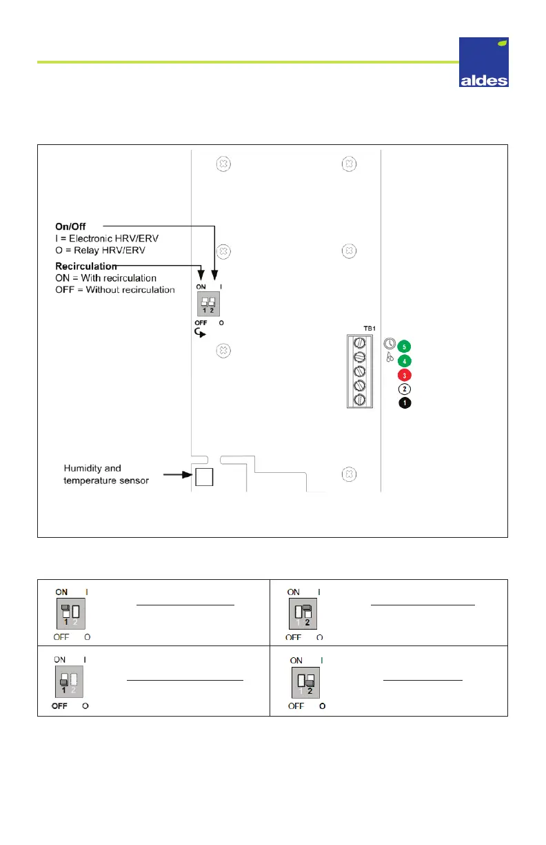
To connect the Digital Multifunction Control to the HRV/ERV, follow these diagrams:
Back of face plate – simplied
Set the ON/OFF switches to correspond to your HRV/ERV model, as listed in the following
table:
With Recirculation
Models: H/E95, H/E150,
H/E190, H/E240
Electronic HRV/ERV
Models: H/E95, H/E110, H/
E150, H/E190, H/E240
Without Recirculation
Models: H/E110
Relay HRV/ERV
Models: None
Connect each wire to the terminal board on the back of the controller face plate according
to the connection chart shown on the mounting plate. Then connect the 4-conductor
wire to the terminal board on the HRV/ERV according to the respective colors. All wires
carry a 24V current.
Aldes Timer Output
Air exchange system, green
Air exchange system, red
Air exchange system, COM
Air exchange system, 24 VAC