Alesis QS Series Keyboards Service Manual V1.00 11/19/06
13
➫ DD0-DD7 Data Buss bits 0 to 7. Correspond to the upper 8 data bits of
the H8.
➫ A0 H8 Address Buss bit 0
➫ RD H8 ReaD enable
➫ WR H8 WRite enable
➫ KEY Chip select line from GAL (Mapped I/O)
➫ KEYINT Output to H8 interrupt line
➫ KEYCLK Clock input from H8
➫ ROW0-7 Row input from keyboard switch matrix
➫ COL0-21 Column input from keyboard switch matrix
➫ VSS1-4 Source Supply (GND)
➫ VDD1-4 Drain Supply (+5V)
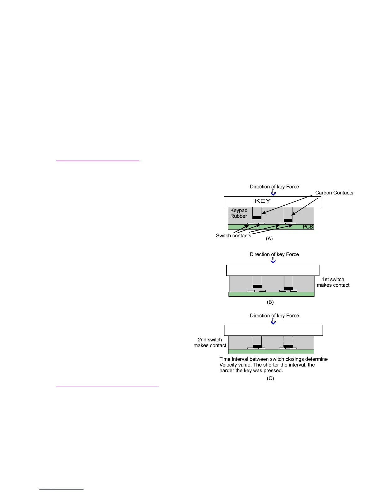
2.34A Reading Velocity
Velocity response is measured through the time differential between two switch closures
and works like this:
➠ The harder a key is pressed, the
faster it moves.
➠ Since Rate = Distance/Time
knowing the time it takes to move
the key through a specific distance
tells us how fast it’s moving and
thus the force acting on it.
➠ This is accomplished by using 2
switch contacts mounted at
different distances from each other.
The rubber in the keypad acts as a
spring, both absorbing the
compression of switch 1, as well as
pushing the carbon contacts away
from the PCB contact points when
the key is release.
➠ The Keyscan ASIC counts up the
time it takes between switch 1
closing and switch 2 closing. Since
distance (between the switches) is
preset in the design, time difference
is taken as a direct measure of
velocity.
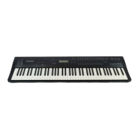
2.34B QS8 Key Construction
All keyboards in the QS Series function
identically in an electrical sense. However, since the QS8 keyboard is different in mechanical
construction from the rest of the line, a word or two about it is appropriate at this point. In order
the simulate the action of a true piano keyboard the FATAR TP/20 keyboard uses moving
metal weights striking a felt strip to emulate the action of the piano’s hammer striking a string.
Figure 5 shows the basic setup of the keys. Note the “action” of the two “levers” involved
in the process. The first lever which is the key itself is single ended, with it’s fulcrum located at
the “back” end of the key. The second lever is the double ended counterweight. With it’s
Figure 4 - Keyboard Velocity Reponse
 Loading...