EasyManuals Logo

Alesis QS Series User Manual

Alesis QS Series
97 pages
To Previous Page IconTo Previous Page
Page #97 background imageLoading...
Page #97 background image
H-88
12.00 Schematics
Note that some revisions are electrically identical to previous versions. In these cases
only the pertinent schematics are provided. Any other changes to the PCBs are outlined in
Section 6.00. Component I.D.s immediately follow each schematic.
Table 14 - Schematic Set
Schematic Revision # of Pages
Comp I.D.?
S6 Main PCB/A A 3 Y
S6 Main PCB/B B 3 Y
QS7/QS8 Main PCB A 3 Y
QS7/QS8 Main PCB B 3 Y
QS7/QS8 Main PCB C 3 N
QS7/QS8 Main PCB D 3 Y
QS7/QS8 Main PCB E 3 Y
QS7/QS8 Main PCB F 3 Y
QSR Main A 3 Y
S6 Keypad A 1 Y
S6 Keypad B 1 N
QS6/7/8 Keypad C 1 N
QSR Front Panel X2 1 Y
S6 Slider A 1 N
S6 Slider B 1 N
QS7/QS8 Slider A 1 N
QSR LCD Module X2 1 Y
QS7/QS8 XFormer A 1 N
QS7/QS8 XFormer B 1 N
QS7/QS8 XFormer C 1 N

Table of Contents

Questions and Answers:

Question and Answer IconNeed help?

Do you have a question about the Alesis QS Series and is the answer not in the manual?
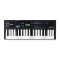
Alesis QS Series Specifications

General IconGeneral
Multitimbral16 parts
OscillatorsSample-based
EffectsReverb, Chorus, Delay, EQ, Distortion
DisplayLCD
MIDIIn, Out, Thru
MemoryUser Programs
OutputsStereo
Weight11 kg

Related product manuals