Alesis QS Series Keyboards Service Manual V1.00 26 11/19/06
4.51 Replacing QS6 And QS7 Keys
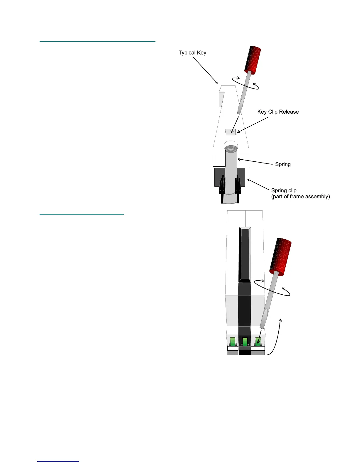
Figure 13 shows the location of the
spring which must be removed before
removing the key itself. It also shows the
location of the key clip release catch. Insert
a flat blade screwdriver into the slot. While
turning the screwdriver to release the catch,
lift carefully at the rear of the key. DO NOT
force the key off or it’s possible to break the
key clip itself, and ruining the entire
keyboard. Once the back end on the key is
loose, slide it towards the front on the
keyboard (range of motion stops are built
into the key and encircle part of the frame).
Putting the new key in is essentially
the reverse process with one small
exception. Instead of using a screwdriver
when putting the rear end of the key back,
just push the rear end of the key down until it
snaps into place.
4.52 Replacing QS8 Keys
Figure 14 shows the location of the key clip release
catch. Insert a flat blade screwdriver into the slot. While
turning the screwdriver to release the catch, lift carefully at
the rear of the key. DO NOT force the key off or it’s
possible to break the key clip itself, thus ruining the entire
keyboard. Once the rear end on the key is loose, lift it
slightly, then slide it towards the front on the keyboard
(range of motion stops are built into the key and encircle
part of the frame). Note: This must be done carefully due to
the spring located under the key (See Figure 5). It is very
easy to loose this spring into the mechanism, where it could
fall out at a later time and cause major damage to the
electronics.
Putting the new key in is essentially the reverse
process with one small exception. Instead of using a
screwdriver when putting the rear end of the key back, just
push the rear end of the key down until it snaps into place.
Note that it may be necessary to remove the first row
(nearest the front of the unit) of keyboard mounting screws
so that the keyboard can be lifted enough to allow the key to clear the bottom panel assembly.
Figure 13 - QS6 Key Release Location
Figure 14 - Key Release Catch Location
 Loading...