Alesis QS Series Keyboards Service Manual V1.00 21 11/19/06
circuit, failures should be relatively easy to troubleshoot although failures with the BUAD
rate circuitry can also affect serial operation.
5. TEST F/X DRAM - This routine forces the F/X ASIC to write to and read from every location
in the F/X DRAM. This will take about 40 seconds. As with the EPROM test above, a failure
here probably indicates a truly faulty DRAM, however a persistent failure (one that occurs
after the DRAM has been replaced) may be in fact due to errors in the F/X ASIC’s
subsystems.
6. TEST SOUND ROM - Like the EPROM Test above, this routine does a checksum of each
of the QS’s Sound ROMs. Again the associated address or data buss failures may appear
as a legitimate Sound ROM failures.
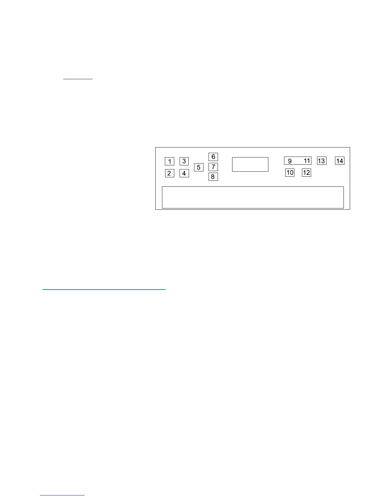
7. TEST SWITCHES - After initiating this test, each front panel button must be pressed in the
correct sequence. This ensures that each button is not only functional, but it also checks for
key debounce errors (i.e. the
unit “sees” the key pressed
several times even though it
was only pressed once). The
sequence starts at the
rearmost left hand button
continues forward, then to the
right (See Figure 7 for an
example).
8. TEST POTS - This test allows the technician to verify the function of the mod and pitch
wheels, as well Data pots or sliders. Once initiated, the LCD will show several numbers.
Each of these numbers represents the position of one of the pots. Data Pots will normally
show a range of 0 - 1023. Pitch and Mod wheels have a range of 0 - 600 and the Aftertouch
has a range of 0 - 300. Moving each pot will cause the corresponding number in the display
to change.
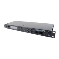
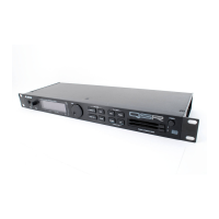
3.13 Differences In QSR Self Tests
Because it is a rack mount unit and it’s buttons are different from the keyboard versions,
the self test routines for the QSR are slightly different. The manual self test (there is no
automated version) is initiated by holding MIDI CH ← and →. Use Cursor ← or → to select the
test to run. Pressing STORE initiates the test. Pressing either cursor button exits the test. Note
that pressing Cursor ← and → shows the current software version, but only if the unit is in MIX
or PROGRAM Play modes (i.e. the unit is not in EDIT or SELF TEST). The tests are:
0. Test EPROM - Same as the keyboard test.
1. Test SRAM - Same as the keyboard test.
2. Test MIDI I/O - Same as the keyboard test.
3. Test PC I/O - Same as the keyboard test.
4. Test F/X DRAM - Same as the keyboard test.
5. Test Sound ROM - Same as the keyboard test.
6. Test Switches - Same as the keyboard test.
7. Test Encoder/LED - Once initiated, front panel LEDs (under the buttons) will cycle
according to the direction the data wheel is turned. Press STORE to exit this test.
8. Test Display - This test simply turns on all of the display elements in the LCD.
9. Test Audio - This test simply sends audio through all outputs. This is extremely useful when
troubleshooting analog circuit problems.
Figure 7 - Examples of Switch Self Test Key Press Order
 Loading...