Alesis QS Series Keyboards Service Manual V1.00 34 11/19/06
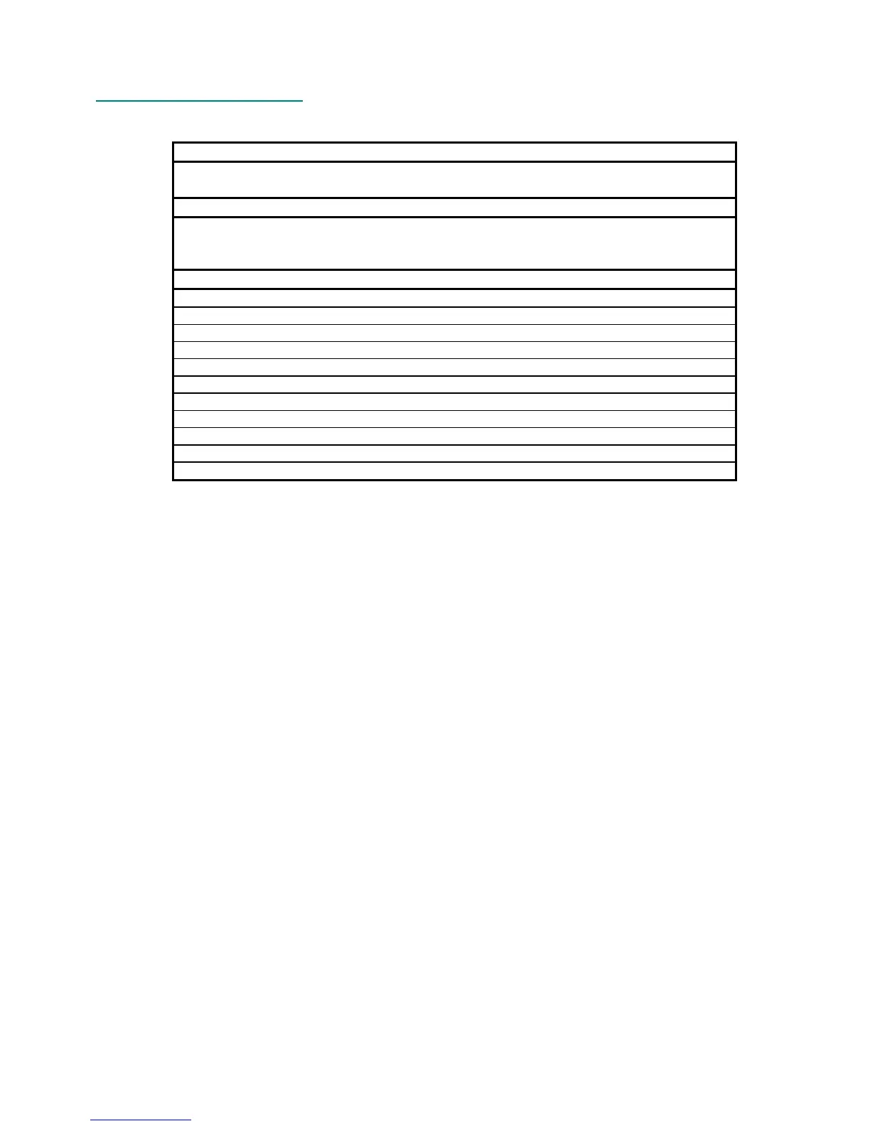
6.15 QS6 Main Revision F
Table 8 - QS6 Main PCB Revision F Changes
PART NUMBER:
9-40-1241
CHANGES FROM REV:
E TO
REV:
F
DATE:
7-22-96
Borders added to PCB at production's request. Now, many back panel parts
become waveable. Because of new waving technology, the audio jacks can be
waved without harm or corrosion. Rev.E and Rev.F are electrically the same.
CHANGE:
Change all text from Rev E to F
Move via from beneath the BNC jack
Straighten trace into headphone jack
Straighten trace above M3
Remove SMK from heatsink
Lower MIDI THRU text
Add .4" border with breakaway tabs on jack side of PCB
Add .15" border with breakaway tabs on keyboard side of PCB
Add fiducials on breakaway borders
Shrink optojack mounting holes to original size
Move the extra hole center to the same level as the bottom right mounting hole
 Loading...