Alesis QS Series Keyboards Service Manual V1.00 35 11/19/06
6.20 QS7/8
6.21 QS7/8 Main Revision B
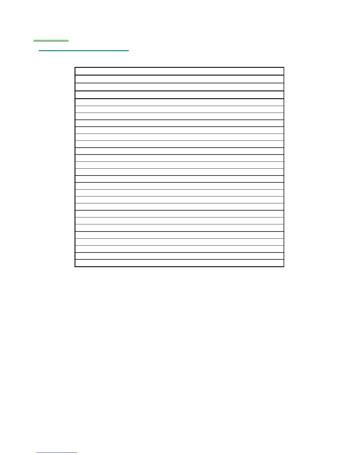
Table 9 - QS7/8 Main PCB Revision B Changes
PART NUMBER:
9-40-1241
CHANGES FROM REV:
A TO REV: B
DATE:
4/15/96
CHANGE:
Change all text from Rev A to B
Reroute 3.072Mhz signal
Add GND bar along back panel
Put GND vias under DACs
Update power diode part
Remove redundant REV.A labels
Move A.T. BLACK silk screen away from edge
Bump up trace below PCMCIA
Move 88 UPPER and 76 UPPER silk screen away from edge
Move D10 and D11 silk screen away from edge
<45 degree angle between J7 and C38
No solder paste for Heat Sink (Use V6 for CAM toppaste)***
Teardrop J21 traces
Adjust C53
Use C4 fiducials
Adjust C46
Add thermals to Heat Sink
Clean up logic
Add 470Ω in series for 3.072Mhz and 12.288Mhz
Plate mounting holes, and completely connect to GND plane
Move 20Mhz crystal closer to uP
Reroute VCO asic area
Move 0.1uF caps closer to power on FX and SG asics
Use 96 mil drill bit instead of 100mil
 Loading...