Alesis QS Series Keyboards Service Manual V1.00 11/19/06
17
2.42 QS7/QS8/QSR D-A
The QS7/8/R Digital-to-Analog Converter is an AKM4319 (U3 U2). A bit clock (BICK) of
3.072 MHz, buffered by a NAND gate acting as an inverter (U12D U10D), is sent from the FX
ASIC (U10 U6). This clock signal is sent to pin 5 of the DAC which is used to latch the serial
data on SDATA (pin 6) into the device. The LRCK (pin 4) input is the left and right channel
clock. This 48KHz clock signal is originated from the FX ASIC at pin 11. SMUTE mutes the
analog outputs and is controlled by the H8 processor (pin 53).
The analog supply (+5V) is filtered by C3 C3 and C7 C8. The digital supply is also
provided from the +5V supply and filtered by C6 C26.
In addition the QS7/8/R use an AUX DAC (U5 U4) for the Aux Output which functions
identically to the Main output.
The DAC outputs are balanced and are routed through differential amplifiers to the unit's
output jacks, via the analog output circuitry (See Section 2.20).
2.50 PC/MAC Serial I/O
As with MIDI, this connector is a serial device with the
majority of the work being expedited by the software running in
the H8. Since there are two basic types of computer in general
use, a great deal of extra hardware is required. As much as
possible, the Alesis design team engineered the circuitry to
reduce the parts count, and combine as much of the two
different types as possible. The IBM compatible PC uses a single
ended serial buss while the Macintosh version uses a balanced
line signal for transmission and reception. In addition, the two
different types require different handshake and BAUD rate clock
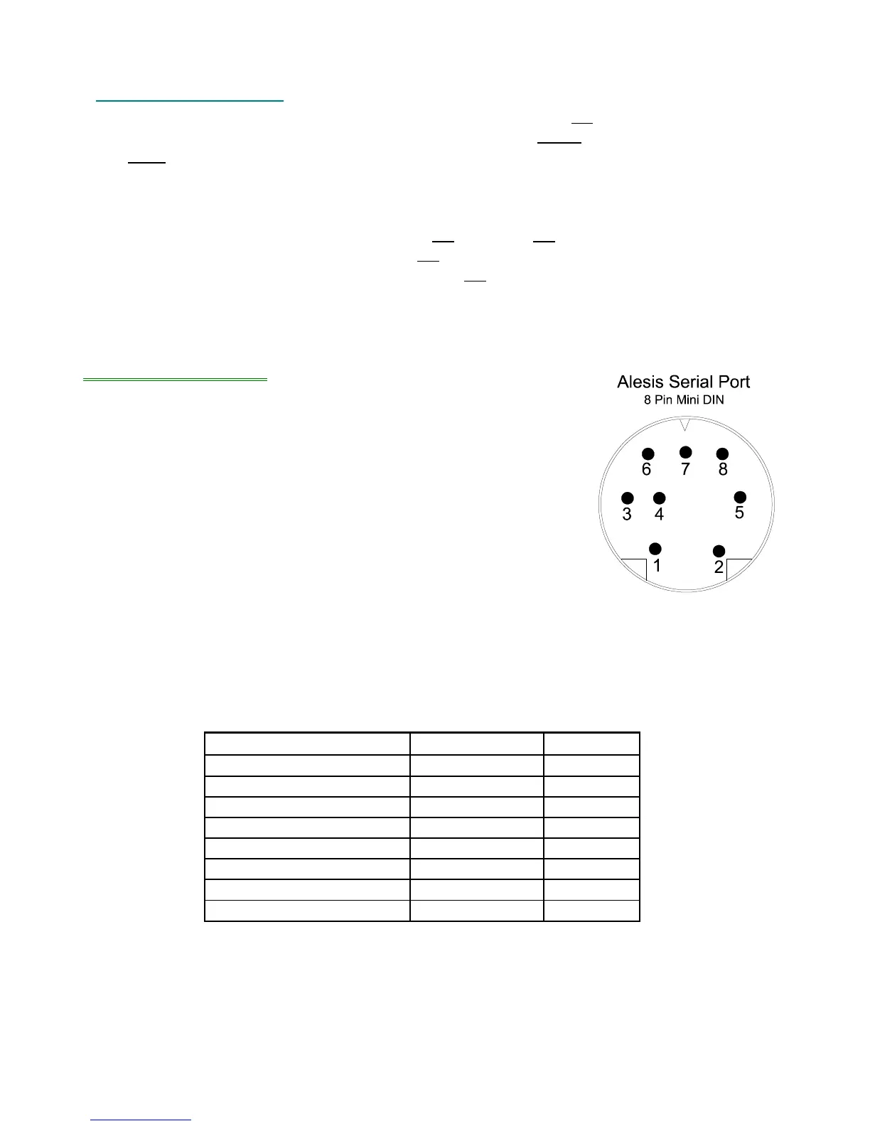
circuitry. Figure 6 shows the pinout of the Alesis QS serial port
and Tables 1-3 show the pin to pin connections of the various
Alesis Serial Cables 1, 2, and 3.
Note that the QS6 is hardware limited to a BAUD rate of 38.4 KHz. All subsequent
designs use software controlled frequency division to achieve a variable baud rate (See
Section 2.54).
Table 1 - Pin to Pin Connections for 9 Pin PC Serial to QS
Purpose QS Serial Pin PC Pin
HSKO (Enable 4-12V) 1 8
Return (Enable Return) 2 7
TXD 3 2
GND 4 5
RXD 5 3
NC 6 NC
NC 7 NC
NC 8 NC
Figure 6 - Alesis Serial Port Pinout
 Loading...