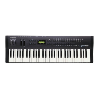
Alesis QS Series Keyboards Service Manual V1.00 11/19/06
ix
List Of Figures
Figure 1 - QS6 Simplified Block Diagram......................................................................................2
Figure 2 - QS7/QS8 Simplified Block Diagram..............................................................................4
Figure 3 - QSR Simplified Block Diagram .....................................................................................6
Figure 4 - Keyboard Velocity Reponse........................................................................................13
Figure 5 - QS8 Key Construction.................................................................................................15
Figure 6 - Alesis Serial Port Pinout..............................................................................................17
Figure 7 - Examples of Switch Self Test Key Press Order..........................................................21
Figure 8 - 48KHz Test .................................................................................................................22
Figure 9 - Keyboard Casetop Removal.......................................................................................23
Figure 10 - S6 Case Screw Locations.........................................................................................24
Figure 11 - QS7QS8 Case Screw Locations...............................................................................24
Figure 12 - QSR Case Screw Locations......................................................................................25
Figure 13 - QS6 Key Release Location.......................................................................................26
Figure 14 - Key Release Catch Location.....................................................................................26
Figure 15 - SG ASIC Pinout ........................................................................................................28
Figure 16 - FX ASIC Pinout.........................................................................................................28
Figure 17 - Keyscan ASIC Pinout................................................................................................29
Figure 18 - H8 Processor Pinout.................................................................................................29
Figure 19 - FX SRAM Pinout.......................................................................................................30
Figure 20 - EPROM Pinout..........................................................................................................30
Figure 21- Sound ROM Pinout ....................................................................................................30
Figure 22 - GAL Pinout................................................................................................................31
Figure 23 - DAC Pinout ...............................................................................................................31
List Of Tables
Table 1 - Pin to Pin Connections for 9 Pin PC Serial to QS ........................................................ 17
Table 2 - Pin to Pin Connections for 25 Pin PC Serial to QS ...................................................... 18
Table 3 - Pin to Pin Connections for MAC Serial to QS .............................................................. 18
Table 4 - QS6 Main PCB Revision B Changes ........................................................................... 32
Table 5 - QS6 Main PCB Revision C Changes ........................................................................... 33
Table 6 - QS6 Main PCB Revision D Changes ........................................................................... 33
Table 7 - QS6 Main PCB Revision E Changes ........................................................................... 33
Table 8 - QS6 Main PCB Revision F Changes............................................................................ 34
Table 9 - QS7/8 Main PCB Revision B Changes ........................................................................ 35
Table 10 - QS7/8 Main PCB Revision C Changes ...................................................................... 36
Table 11 - QS7/8 Main PCB Revision D Changes ...................................................................... 36
Table 12 - QS7/8 Main PCB Revision E Changes ...................................................................... 37
Table 13 - QS7/8 Main PCB Revision F Changes....................................................................... 37
Table 14 - Schematic Set............................................................................................................ 88

 Loading...