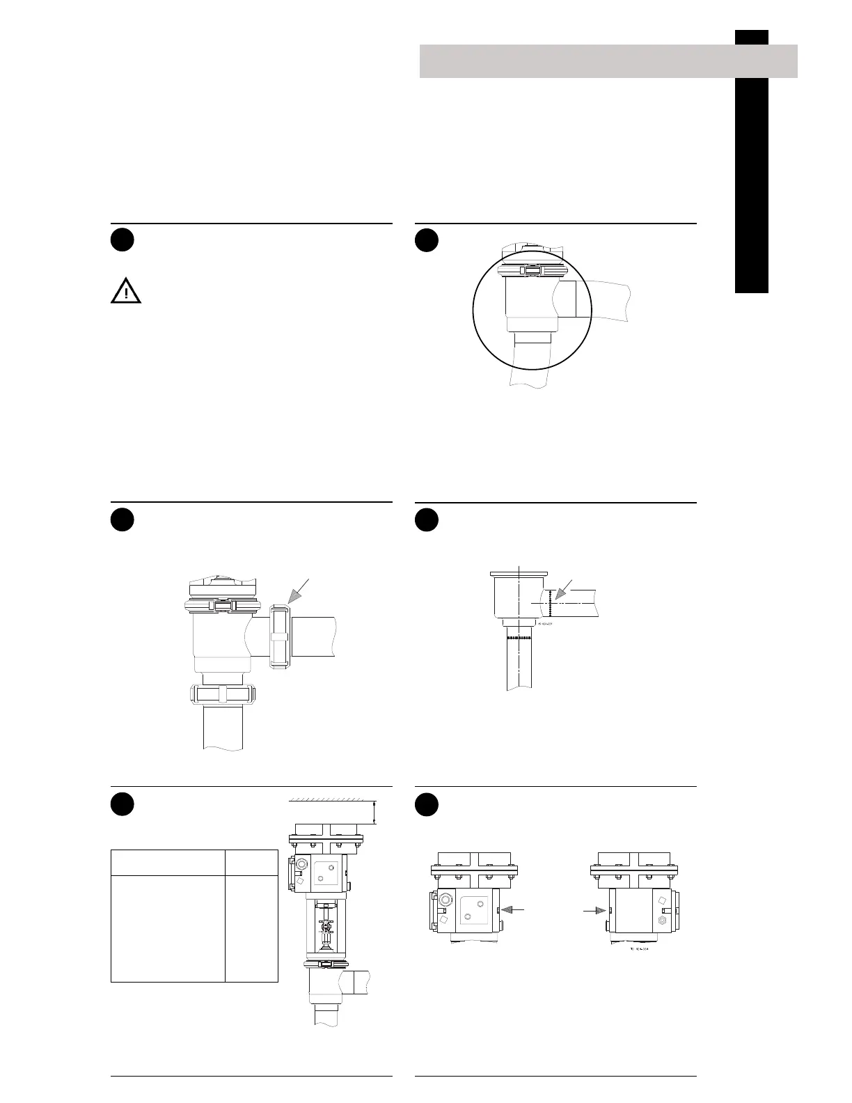
5
Dimension A (mm)
38mm/DN40 100
51mm/DN50 105
63.5mm/DN65 130
76mm/DN80 145
101.6mm/DN100 180
1
3
5
Remember seal rings!
4
2
6
Weld carefully!
Installation
Study the instructions carefully and pay special
attention to the warnings!
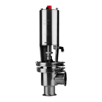
The valve has welding ends as standard but can also
be supplied with fittings.
2. Installation
Avoid stressing the valve.
Pay special attention to:
- Vibrations.
- Thermal expansion of the tubes.
- Excessive welding.
- Overloading of the pipelines.
Fittings:
Ensure that the connections are tight.
Welding:
1. Remove the internal valve parts in accor-
dance with instruction 1 on page 12.
2. Weld the valve into the pipelines.
3. Assemble the valve in accordance with in-
struction 5 on page 13.
Welding into a manifold:
Maintain the minimum clearance (A) so that the
actuator can be removed.
Electrical connection:
1. Remove the black cover from the actuator.
2. Fit the cable through the cable gland and
connect it to the terminal strip. Ensure
correct polarity (11 = +,12 = -)!
3. Tighten the cable gland and refit the cover.
- Always read the technical data
thoroughly (See page 14).
- Always release compressed air after
use.
CAUTION!
- Always let the valve be electrically connected
by authorized personnel.
- The I/P-converter of the actuator is adjusted
before delivery and must never be opened.
NOTE!
We cannot be held responsible for incorrect
installation.
Risk of damage!
A
Cover for
electrical
connection