7
1
3
4
2
Operation
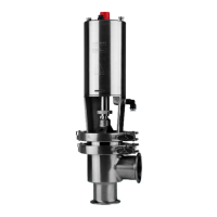
3. Adjustment of the valve
The valve is adjusted and tested before delivery.
The adjustment instructions on this page are only to
be used if further adjustment is required!
Study the instructions carefully.
Calibrate with care.
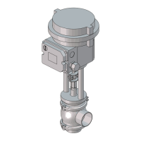
1. Loosen and remove clamp fitting (9).
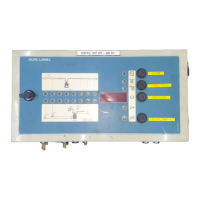
2. Remove the cover from the terminal box.
3. Fit air fittings in entry 9 on the actuator.
4. Supply compressed air (4 bar) to the air fittings.
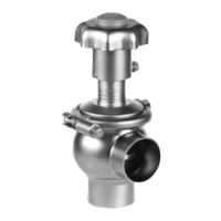
1. Set the highest signal (20 mA), + on ter-
minal block 11 and - on terminal block 12.
NOTE!
For NC valve the signal must be 4 mA.
2. Make sure that valve plug (2) is pressed
against the valve seat.
1. Adjust valve plug adjuster (7) so that it
contacts the actuator piston rod. (Give 1/4
extra turn to give preforce on the plug).
2. Tighten lock nut (8) using a spanner.
3. Fit and tighten clamp fitting (9) to connect
the actuator piston rod with valve plug (2).
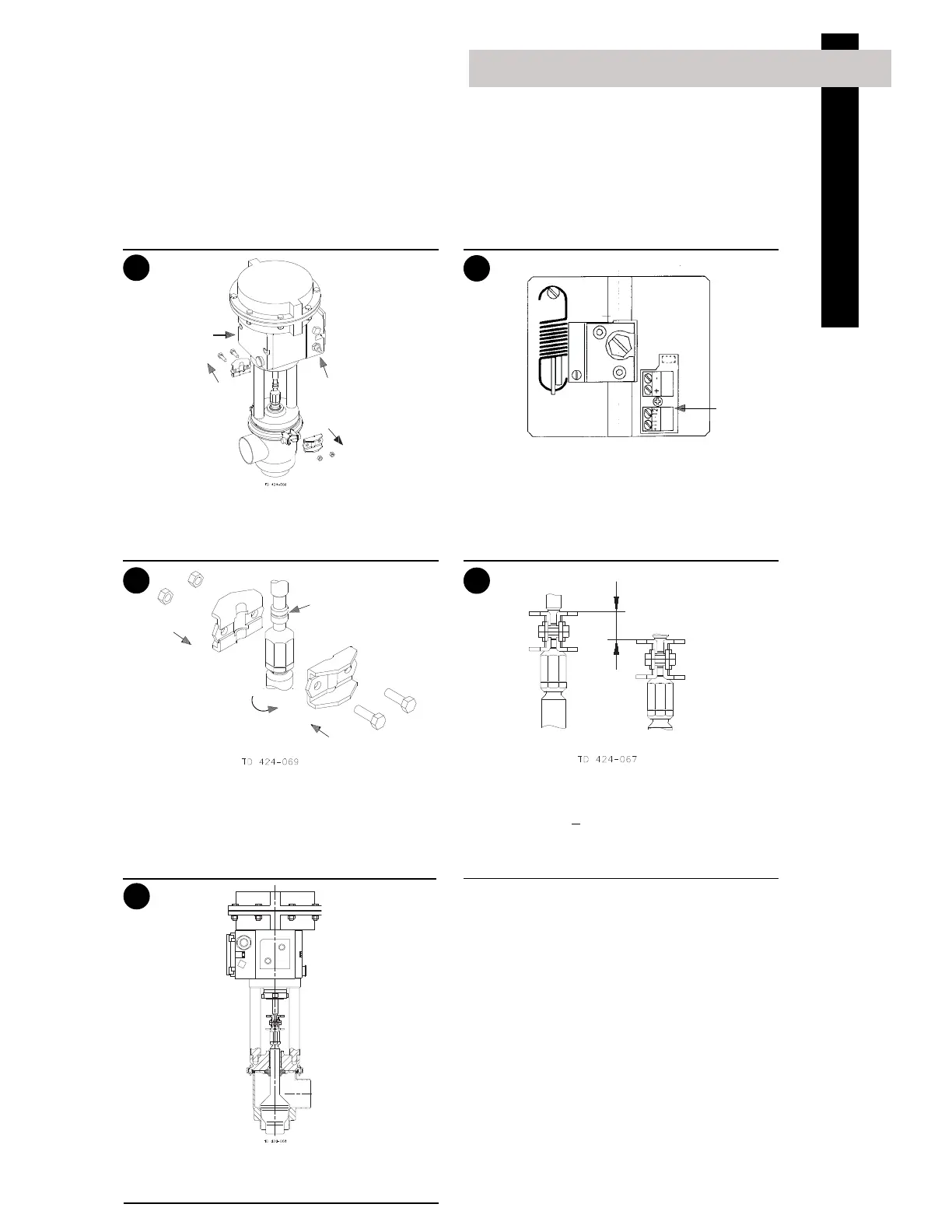
Check the stroke by changing the signal from 20
to 4 mA (NO) (Opposite if NC).
Stroke = 20 mm
+ 1.
NOTE!
In case of deviation from 20 mm stroke, see
page 8.
5
Move valve plug (2) up and down several times and
check that the valve plug is still in closed position.
If not, readjust.
Terminal box
Supply air
Terminal
blocks
Contact
Stroke = 20 mm±1
 Loading...