8
Wiring diagram!
Installation
3
5
1
2
4
6
Turn the
drain holes
downwards!
1. Fit the indication unit on the bracket.
2. Tighten the screws.
Study the instructions carefully.
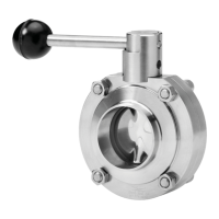
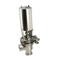
LKLA-T: For top units LKT-N and LKT-S.
Activating ring: For ø85mm actuator.
Indication pin: For ø133mm actuator.
Activating screw: For ø133mm actuator.
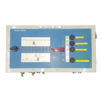
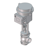
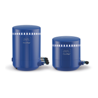
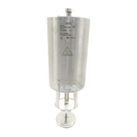
5. Indication and control equipment (optional extras)
Turn the cable outlet
downwards!
Tighten screw (6) firmly.
NOTE!
The cable gland with seal ring (3) should be
sealed with silicone rubber under extreme condi-
tions.
CAUTION!
The indication and control equipment must be
electrically installed by authorized personnel.
- Indication unit:
(See the instructions on the unit and on the
packing).
- ThinkTop
®
:
(See the separate instruction manuals).
NOTE!
Assemble the cable socket as shown on the
plastic bag.
Parts: (See the plastic bag)
1. Gland screw.
2. Gland washer.
3. Seal ring.
4. Hood.
5. Insert.
6. Screw.
7. Seal.
Connect the cable as shown in the wiring diagram
on the indication unit.
ø85mm
Common 1
3 Closed
valve
2 Open
1. Fit the bracket, the activating ring/indica
tion pin and the actuator/handle corretly
before installing the indication unit.
Pay special attention to the warnings!
(See instructions 1-6 on page 7).
2. Fit the activating screw correctly
(ø133mm).
LKLA - ø133mm
LKLA - ø85mm
Screw
Ring
Artisan Technology Group - Quality Instrumentation ... Guaranteed | (888) 88-SOURCE | www.artisantg.com
 Loading...