5
1
3
5
4
2
6
Study the instructions carefully.
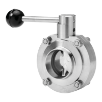
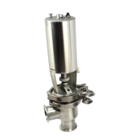
The valve has welding ends as standard but can also
be supplied with fittings (not LKB-F).
NC = Normally closed.
NO = Normally open.
A/A = Air/air activated.
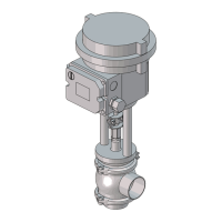
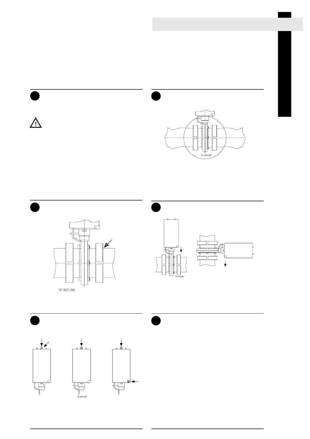
2. General installation
Installation
Air connection of actuator:
Connect compressed air correctly.
Pay special attention to the warnings!
NC NO A/A
Air Air Air
R1/8"(BSP)
Position of actuator:
Position the water rejector on the actuator
correctly. (The actuator can be installed in any
position).
Turn the ventilation
opening downwards!
Fittings:
Ensure that the connections are tight.
Remember
seal rings!
Avoid stressing the valve.
Pay special attention to:
- Vibrations.
- Thermal expansion of the tubes.
- Excessive welding.
- Overloading of the pipelines.
Risk of
damage!
NOTE!
We cannot be held responsible for incorrect
installation.
- Always observe the technical data
(see page 20).
- Always release compressed air after
use.
- Never touch the coupling between the
valve body and the actuator if compres-
sed air is supplied to the actuator.
Pre-use check:
Open and close the valve several times to
ensure that the valve disc moves smoothly
against the sealring.
Pay special attention to the warnings!
Artisan Technology Group - Quality Instrumentation ... Guaranteed | (888) 88-SOURCE | www.artisantg.com
 Loading...