4 Installation
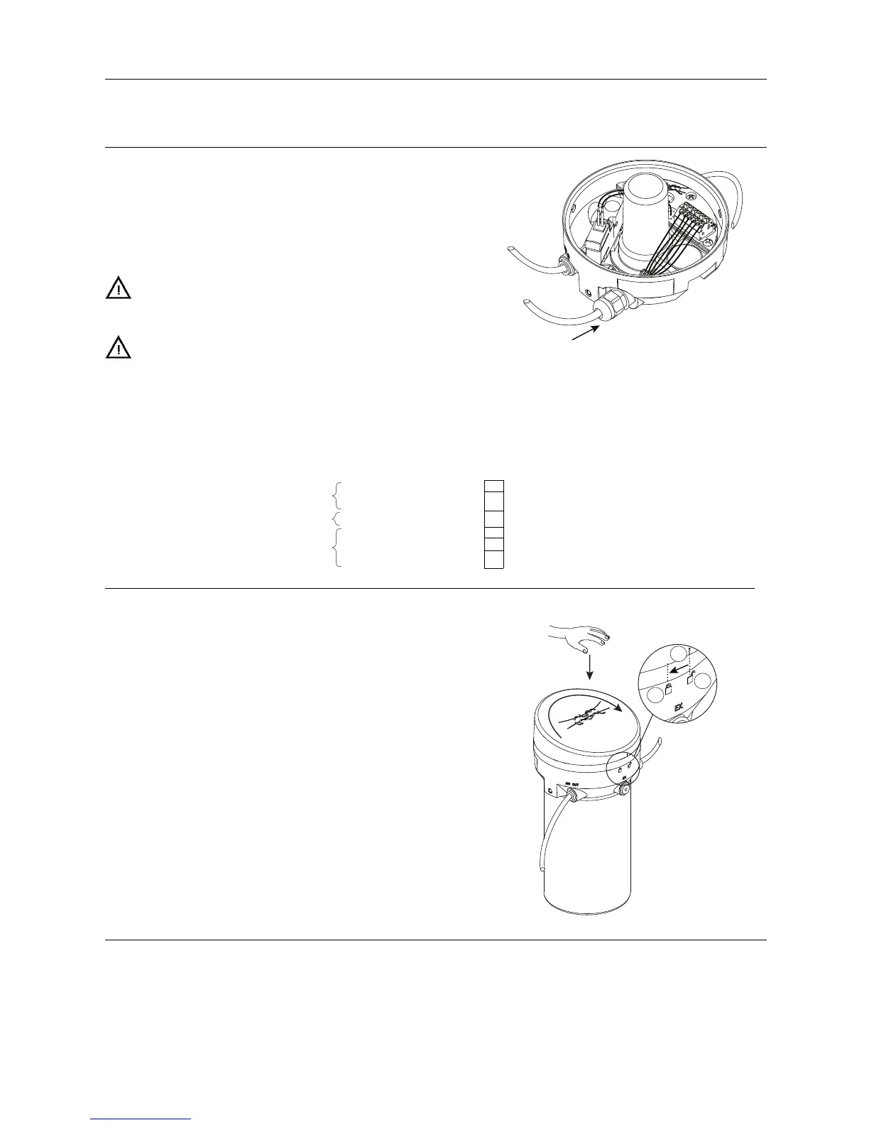
Step 4
Install the cable in the cable gland.
NOTE
Cable connection
Cable gland: PG7 (cable dia. ø4.0 - ø6.8 mm)
Recommended conductor
cross section:
0.5 mm
2
(AWG 20).
If the cable gland comes loose from the control head during
installation, it must be secured with a tightening torque of 1.50 Nm.
To fulfil the UL requirements in UL61010, the unit must be supplied
by an isolating source that complies with the requirements for class
2 power units (UL1310) or class 2 and 3 transformers (UL1585).
2064-0005_1
Electrical connection
Digital Interface
Sensor board
Terminal strip
GND
-
Connection of power supply
24 VDC
+
PLC output signal
Trigger solenoid
T
Alarm A
De-energised
D
PLC input signals
Energised
E
Step 5
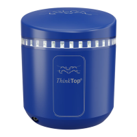
Put the top cover back on by pushing it down when the mark on
the top cover (E) and the open padlock (F) are aligned.
Then turn it clockwise towards the closed padlock (G) to secure
the top cover.
2064-0007
E
F
G
9