3 Installation
Study the instructions carefully and pay special attention to the warnings!
Thevalvehasendsforweldingasstandard.
Weld carefully/aim at stressless welding to avoid deformation on sealing areas.
Check the valve for smooth operation after welding.
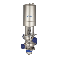
Step 6
It is important to connect CIP inlet to the small inlet nozzle to avoid
built-up pressure in the cleaning chamber.
CIP in CIP out
TD 449-127
Align nozzle e
dges with recess in sealing element.
3.3 Welding
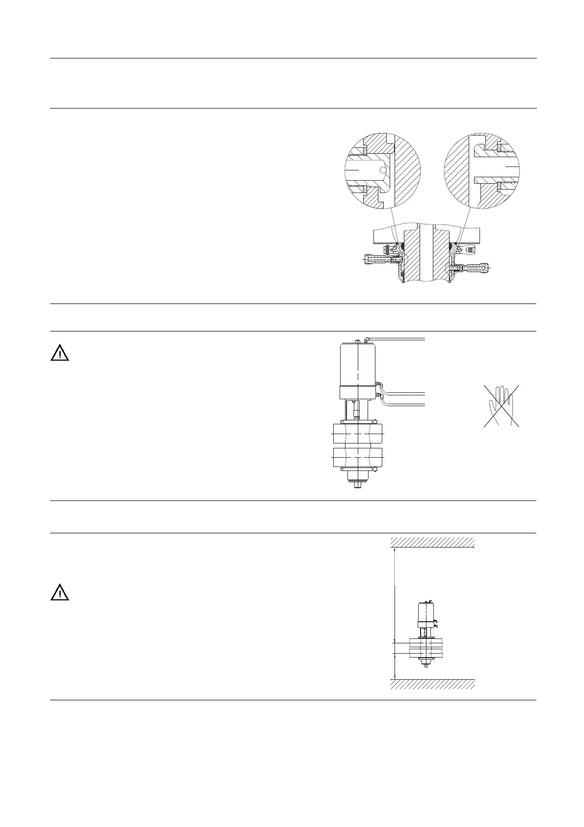
Step 1
Never stick
your fingers through the valve ports if the actuator is
supplied with compressed air.
Cutting danger!
Air
TD 449-325
Step 2
Dismantle the valve in accordance with Step 1 in section 5.2 Dismantling the valve.
Step 3
NOTE
Maintai
n the minimum clearances so that the actuator with the
internal valve parts can be removed - please see later this section!
If there is a risk of foot damage, Alfa Laval recommends to leave
adista
nce of 120 mm (4.7”) below the valve (look at the specific
built-in conditions).
C
B
TD 449-024_1
12