6
when the radiators are submerged and where in case of termination of the pump operation for any reason, the water
temperature in the boiler rapidly increases and overheating occurs very quickly.
In the open central heating system, installation of thermal fuse is not mandatory.
7.2. 1 . THERMA L VA LVE W ITH BU ILT -IN TH ERMAL PROT E CTION (Fig. 7, Item 13 and Fig. 7a )
Thermal fuse is installed near the solid fuel, depending on the available space. It can be installed in any position. You
should take into account the direction of cold water intake and hot water outlet from the boiler which is clearly marked on the
valve body.
The thermal fuse probe (Fig. 7, Item 22) is best to place in the thermal valve connection (Fig. 7, Item 18). It can be placed
on the discharge - distribution pipe (Fig. 7, Item 3) but at a distance from the boiler of 500 mm the most or at the highest point
of the boiler before the exhaust pipes.
Seal it with hemp or other sealing material by tightening.
Fig. 7 shows the thermal valve installation diagram.
The device is of one piece with the thermal valve and valve for filling.
Valve opening temperature is 100°C (+0°C/-5°C).
The fluid recommended in the installation is water and glucose antifreeze of 30%.
Note:
At reaction, and valve operation, during fluid cooling in an overheated boiler part of the new fluid is injected into the boiler,
but the part is also ejected from the boiler. It will be poured down the drain. If the antifreeze is in the installation you must
keep in mind that a certain percentage will go out and pour down the drain!
We recommend the thermal valve Caleffi type 544, 1/2" as shown in Figure 7a.
7.2. 2 . SL OPE PRESSU RE RE GULA T OR 1/2 " WITH MA NOMETE R (Fi g. 7, Ite m 19 and Fig. 7 b)
When installing the thermal valve it is required to mount the slope pressure regulator as shown in Fig. 7, Item 19. The
pressure that is maintained by pressure regulator must be set at a higher pressure than the pressure that is in the heating
system. If you do not have a higher water pressure of at least 0.8 bar compared to the pressure in the heating system thermal
valve will not work or cannot inject cold water into the boiler that needs to be cooled.
Pressure regulator should be set to 2.8 to 3 bars.
You should take into account the direction of placing the slope pressure regulator
7.2. 3 . WATER FILTE R O F THE BOIL ER INT AKE ( Fig. 7 , Item 2 0)
In front of the slope pressure regulator on water intake from water supply line it is necessary to install a filter that will clean
the water from solid objects, primarily of sand, which can damage the tap seal or seals of the thermal valve and the slope
pressure regulator.
This filter does not need to be resistant to high water temperatures due to cold water that flows through.
7.2. 4 . WATER FILTE R OF THE B OILE R OUT LET (F ig. 7, Item 21 )
It is required to install the filter on the boiler outlet which will clean the hot - boiling water from dirt and solid objects that
can damage the tap seals, or seals of the thermal valve.
This filter must be resistant to water temperatures up to 150°C.
NOTES:
- After the completion of thermal valve activation, checking the pressure in the installation and filling the system with cold
water is mandatory.
- In cases where antifreeze is used, after filling the installation with water it is required to check percentage content of
antifreeze in a mixture of water and antifreeze!
- To avoid elimination of the antifreeze agent solution from the installation, it is best to have backup battery supply of the
pump with an inverter.
7.3. SAFETY VALVE (fig. 7 and 8 pos. 5 and fig. 4 pos. 6 )
On the back side of the boiler under the hob, a connection R1/2" is welded (fig.4 pos.6) in which you are OBLIGED to set a
safety valve. The safety valve should be between 2,5 to 3 bar. It can be installed directly on the terminal or at a distance from
the solid fuel of 1m the most, provided that there is no block valve between the boiler and the safety valve.
In an open heating system, the safety valve is not put normally, but we advise that you put it as one more type of insurance
of the boiler and the system (due to unforeseen circumstances).
WARNING:
If the safety valve is not set as previously explained, the guarantee ceases.
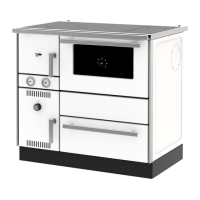
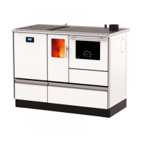
7.4. THERMOMETER AND MANOMETER (fig. 1 pos. 16 and 17 and fig. 5)
On the solid fuel itself, on the additional cover (fig.1 pos.24) between the firebox door and the ashtray door, thermometer
and manometer are mounted (fig.1 pos.16 and pos.17, and fig.5) so they do not have to be placed on the installation.
The thermometer pos. 17 shows the temperature of water in the boiler (operating temperature) in °C.
The manometer pos. 16 shows the water pressure in the boiler, that is, in the system, in bars.