Do you have a question about the Alinco DR-112 T and is the answer not in the manual?
Lists external components for the transceiver chassis.
Details screw types and sizes used in cabinet assembly.
Adjusting VCO voltages and radio frequency settings.
Setting transmitter power output and RF power meter levels.
Tuning audio deviation, mic gain, and tone settings.
Adjusting squelch sensitivity and S-meter operation.
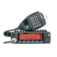
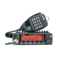
| Frequency Range | 144-148 MHz |
|---|---|
| Modulation | FM |
| Receiver System | Double conversion superheterodyne |
| Voltage | 13.8 V DC |
| Antenna Connector | SO-239 |
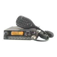
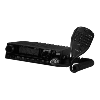
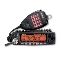
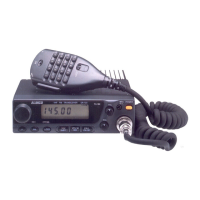
| Type | Mobile FM Transceiver |