ALLEN & HEATH
Section A - 11
L4DSM2
ASSIGNING AN INPUT CONNECTOR CIRCUIT BOARD ASSEMBLY
Before fitting a replacement input connector circuit board assembly, check the assignment of the channel mutes is
correct. If possible check the circuit board assembly with the one that has been removed.
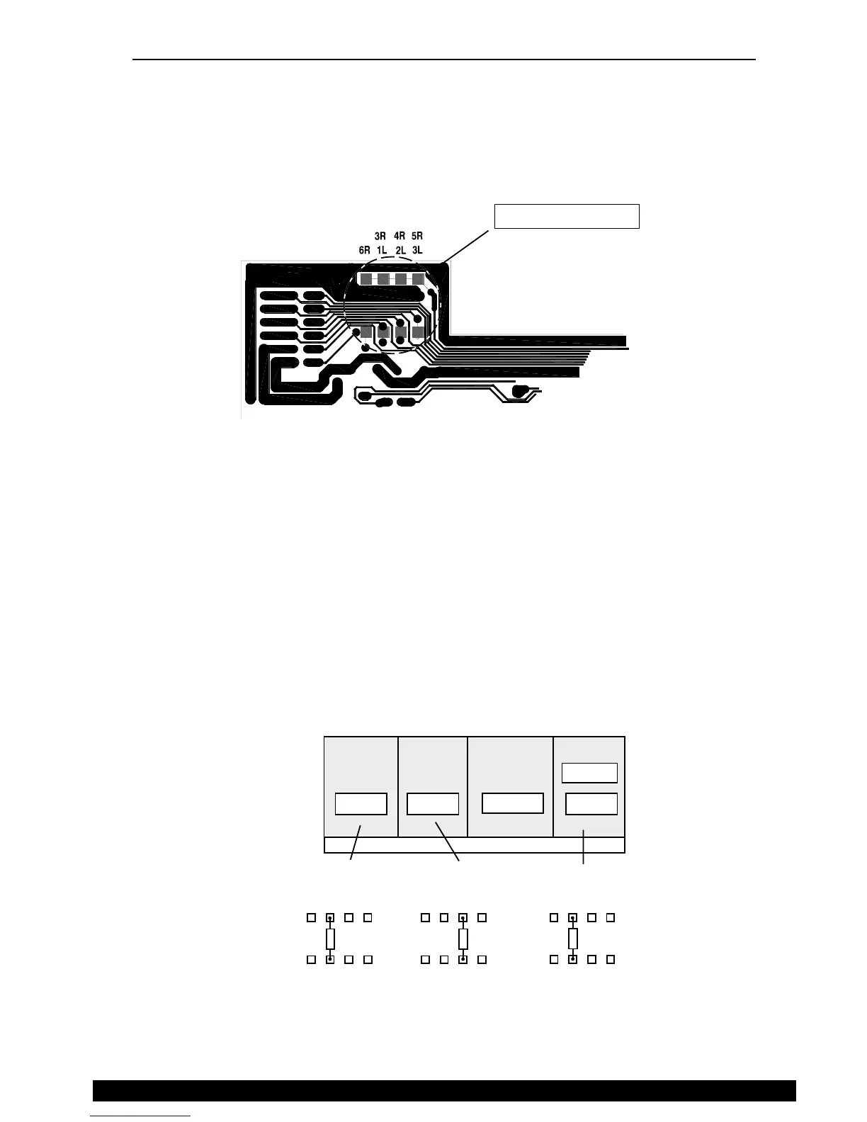
The assignment links are zero ohm (0R) resistors and are located near to the ribbon harness connector on the input
connector board.
The channel mute assignment is set by soldering a 0R resistor into one of four locations. see below
Input connector
circuit board
Assignment links
track side view
GL4000-824S
GL4000M-824n
(Stereo configurations differ)
MASTER
1 - 8
17 - 24
stereo
9 - 16
6R6R
5R
3L
4R
2L
3R
1L
5R
3L
4R
2L
3R
1L
6R
5R
3L
4R
2L
3R
1L
The diagrams below show the channel mute link assignments for the input connector circuit board assemblies for each
console format.
Remember when adding an expander to the console the assignment of the links in the console may also require
reassigning. Refer to the expander fitting instructions (AP2794).
 Loading...